This thread has been locked.

If you have a related question, please click the "Ask a related question" button in the top right corner. The newly created question will be automatically linked to this question.

OPA182: OPA182IDR

Part Number: OPA182
Other Parts Discussed in Thread: OPA187, OPA333, OPA192

Hello

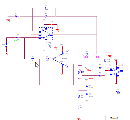
To get an image of the current, I would like to use the OPA182IDR in a differential circuit.
This calls for the use of a Zero DRIFT amplifier since the remeasurement needs to be exact less than 100uA.

Do I need an output filter to cut the 200KHz chopping frequency because I've never used this kind of amp?

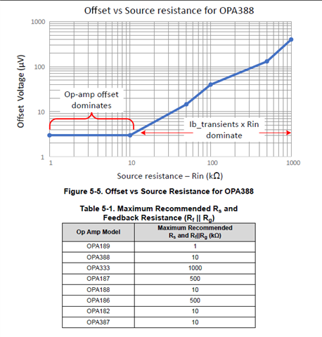
Is it correct that, in my case, I'm using considerably higher resistance values than what the sboa586 application note indicates—that Rs and Rf//Rg = 10KR?

Is the system's input impedance adequate?

Thank you for your help

  • Hi DRUIHLE,

    The resistor component values on the schematic on the right side are not readable since they appear very blurry. Can you please kindly attach a higher resolution schematic that shows the resistor values so we can review the circuit?

    As described on page 18, Figure 5-1 and Table 5-5 of the application note of the SBOA585 White Paper, the flat region on the left-hand side of the plot is where the inherent offset of the amplifier is dominant. The region where the curve increases with source impedance is where the current transients dominate the offset. The recommendation is to not configure the choppers amplifier with larger source impedances where the transients dominate over the offset specification of the amplifier. Per table 5-5, for the OPAx182, IF the calculated equivalent resistance at the input terminals of the OPAx182 exceeds 10kΩ, the current transients dominate the op-amp offset spec, and the device will show larger offset, offset drift and noise.

    Please re-attach a higher resolution schematic that shows the resistor values so we may review the circuit.

    Thank you and Regards,

    Luis


  • Druilhe,

    I cannot read the details on your schematic.  However, if your source impedance is greater than the recommended impedance you should look for an alternative op amp.   One option with the same supply range as OPA182IDR is OPA187.  This device tolerates impedances up to 500kohm.  If you use the OPA182 with impedances greater than 10k, you will translate the bias current transients of the amplifier into Vos beyond the OPA182 specifications.  If the OPA187 does not work for your application you should consider a non-chopper amplifier with good DC characteristics. 

    In your original post you mentioned that the measurement needs to be less than 100uA.  Did you mean 100uV?  The topology of your circuit looks like https://www.ti.com/lit/ug/slau507/slau507.pdf .  This design used OPA333 so I think you are driving towards a similar solution.   Since these types of applications generally do not require much bandwidth the OPA187 should work fine.  Also, a good linear amplifier like opa192 is a good option.

    Art

  • Thank you. The OPA187 seems like an excellent fit. Where can we locate the 500 kohm suggested impedance in the datasheet?

    The measurement's precision is said to be +/-100µV.

    Thank you for your assistance.

  • Schéma OPA182.docx

    Although there is a clear diagram included, the input impedance is in fact higher than 10K.

    Thank you and Regards,

  • Druilhe,

    The 500kΩ limit is not in the data sheet.  The app note https://www.ti.com/lit/wp/sboa586/sboa586.pdf that includes this information was just released in the past few days.  The key point of the app note is that the chopping Ib transients translate into an additional offset.  The specific maximum resistance that can be used for different choppers was not available until this app note was developed.  I expect that future chopper product data sheets will include this information, but for all the existing products you need to use the app note to find this value.

    best regards, Art