This thread has been locked.

If you have a related question, please click the "Ask a related question" button in the top right corner. The newly created question will be automatically linked to this question.

LOG112: LOG112 application problem

Part Number: LOG112

Hi Ti colleague,

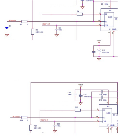
We are long customer to use LOG112. Now we want to fulfill redundancy LOG112 output circuits for one sensor, as attachment drawing. One sensor's current is split into two / redundancy LOG112.

Now we found that the two LOG112 will output differently too much, for example one output 2.1V while another output 0.5V, so can not realize redundancy. We find that in several samples if we increase the input resistance R7/R29 value to 1K Ohm or 750 Ohm (keep R7 = R29), then two channels output almost same voltage that different small than 0.03V and acceptable.

But is there some bad effect that input resistance brings? For example stable, frequency response ....

Thank you very much in advanced!

  • Hi Jianmin,

    Adding a series resistance R7/R29 of 1kΩ may help isolate the capacitance on the IR sensor, helping with stability, but the voltage at the output of the IR sensor will change as the current output sensor changes, depending on how the IR sensor is connected and the type of sensor.  Some sensors have a voltage output requirement limited by the supply.  

    The most common way to compensate the LOG112 for stability is to adjust the compensation capacitor Cc, between VLOGOUT and I2:

    Page 6 of the LOG112 datasheet offers a suggestion for the minimum compensation capacitance (Cc) as a function of the LOG112 I2 and I1 current:

    1)  Do you have a data sheet or information with specifications for the IR sensor?  What is the current range expected for the IR sensor in this application? 

    2)  Can you please post the complete schematic of the LOG112 showing the VCM connections and auxiliary amplifier connections, and the IR sensor connections?  What is the value of resistors R4 and R27?

    Thank you and Regards,

    Luis 


  • HI Jianmin,

    In the application above are the LOG112 amplifiers connected to independent IR sensors or to the same sensor? If both LOG amplifiers connect to the same IR sensor, this will not work well as any small offset and common-mode error mismatch of the amplifiers will likely produce a very large error.

    Thank you and Regards,

    Luis

  • Hi Luis,

    Thank you very much for your prompt feedback!

    I am confused on two reply. According to your 1st replay and my report, we find that if we increase the input resistance R7/R29 value up to 1K, when two LOG112 amplifiers are connected to same sensor as drawing, then there is no malfunction problem as the second reply remind on large mismatch. Could you confirm that if it is OK or not theoretically / practically?

    For the sensor detail and working current, could you provide your TI E-mail since that those information could not be public from company policy. Thank you very much!

    Best regards,

    Jianmin

  • HI Jianmin, 

    On the first reply, I was considering that these were completely separate redundant circuits using separate IR sensors. The resistance comment was regarding the effect of the series resistance isolating the sensor capacitance, where in some cases, it 'may' help with stability. Nevertheless, as explained in the reply, the Cc capacitor is typically adjusted to compensate for stability.  This discussion is only for the case of separate IR sensors for each log amplifier on a completely redundant circuit. 

    The logarithmic amplifier converts an input current to an output voltage, and behave in similar fashion to transimpedance amplifiers. Two logarithmic amplifiers will not work properly when connected to the same current output sensor.  The IR sensor produces a current output, and we can't assume the current to split evenly between the amplifiers. You will likely see large errors, specially at the low current ranges, and as a function of the offset mismatch between the LOG amplifiers, as the input terminal of each LOG amplifier is set to a slightly different voltage, and will stir current though the series resistors.

    You can contact me via private conversation on E2E and share the schematic and IR sensor spec; but you will likely need to use separate IR sensors for a fully redundant circuit, or the use of an additional circuit to copy or mirror the IR current prior feeding into the LOG amplifiers.   

    Thank you and Regards,

    Luis

  • Hi Jianmin,

    I have contacted via private message, and will continue the discussion via private conversation per your request.

    Thank you and Kind Regards,

    Luis

  • Hi Luis,

    Thank you very much!

    I have introduced our draft version through the private message, hope to get your professional feedback.

    Morning and happy work ~~~

    Best regards,

    Jianmin

  • Hello Jianmin,

    I have received your schematic, and will continue the conversation through private discussion. 

    Thank you,

    Kind Regards,

    Luis