


Hello,
I am trying to design a highly sensitive transimpedance amplifier (TIA) system to amplify very low modulated current levels of a photodiode (order of ~10 nA peak-to-peak). This is my first time simulating/designing an analog circuit and it has been a rewarding challenge so far.
I recently went through the TI "Precision labs series: Op amps" video series to educate myself in the basics of analog design. One of the units within the series covers the fully differential amplifier (FDA). Upon seeing the videos and how FDAs excel at removing common mode noise between the inputs, I thought it has potential for being used as a highly sensitive TIA. What I originally envisioned was the following circuit for a FDA-TIA system:
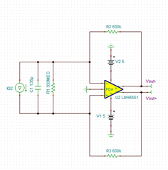
Where the current source IG2, capacitor C1, and resistor R1 is equivalent photodiode model for my system. Is there any inherent issues in using an FDA like a TIA? (Note: I simply used one of the macro models available on TINA TI for illustration purposes... I have not done any simulations as I am still learning how to properly simulate an FDA with TINA TI.)
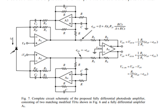
I scoured online to see if anyone has tried using a FDA directly coupled to a photodiode... but nothing came up. The closest thing I could find was from literature published by Zhang et al. (2019) https://doi.org/10.1364/OE.27.002125 where they convert the photodiode into a voltage signal first using TIAs and then couple the output voltages to a FDA as shown below. Is it a rule of thumb to only be able to use a voltage source/input for a FDA?
I also have a question regarding actually measuring the differential output (ΔVout) of the FDA to a single input instrument such as a lock-in amplifier. If I wanted to measure ΔVout using a single input device, would I have to couple the FDA outputs to a single ended op-amp in a differential configuration first, then measure the single ended output? Measuring ΔVout with a multichannel oscilloscope seems quite easy as I can plot the difference of Vout- (input channel 1 on oscilloscope) and Vout+ (input channel 2 on oscilloscope) using a basic difference math operator on the oscilloscope. TIA_VS_FDA.TSC


