This thread has been locked.

If you have a related question, please click the "Ask a related question" button in the top right corner. The newly created question will be automatically linked to this question.

SOT23-UNIV-AMP-EVM: PWM SIGNAL GENERATION FREQUENCY

Part Number: SOT23-UNIV-AMP-EVM
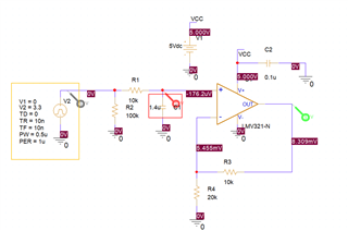
Other Parts Discussed in Thread: LMV321-N

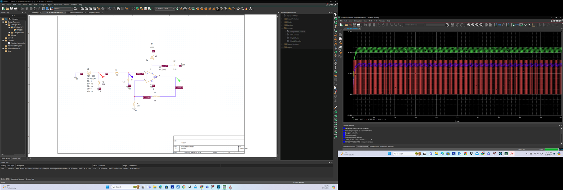
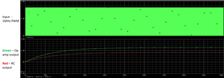
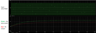
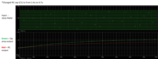
I am confused about the frequency for the PWM signal coming in. It is between 0 and 3.3 V. The C1 and R1 form a low pass filter. Which I calculated to be 33 Hz, so I thought I''l keep my frequency for the PWM signal to be 25Hz, but the response is much clean with a higher frequency...I though it should just cut the higher frequecy PWM off right. Why is this happening? what should I set the frequency of my PWM to. I am aiming for 4.25 V output, hence the duty I calculated was 86%.

  • Hi Jenil, 

    Welcome to E2E! 

    To remove the ripple effect on the output, there are two factors impacting - the PWM signal frequency and the capacitor of the RC filter. I recreated the circuit using the LMV321-N (I could not fully see the part number in the screenshot so I took a guess which part this was.) 

    The faster the PWM signal, the less amplitude of the ripple. If you use a very fast PWM signal (f = 1MHz below to illustrate), you can see the ripple is minimal.  

    Versus a 1kHz signal: 

    The RC filter impacts the settling time of the final value. In the above two simulations, I lowered the capacitor value so the RC filter time constant is decreased. When using a larger capacitor (4.7u vs 1.4u), it takes longer for the output to settle. 

    These are the two main tradeoffs to consider and should test in simulation to see what works best for your application. 

    Please let me know if you have further questions.

    Thank you!

    Best Regards,
    Ashley