This thread has been locked.

If you have a related question, please click the "Ask a related question" button in the top right corner. The newly created question will be automatically linked to this question.

OPA855: A high pass filter

Part Number: OPA855

Hello,

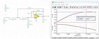
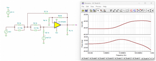
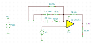
I want to design an active high pass filter using OPA855 which starts amplifying arounf 45MHz and stops around 100MHz. I tried Sallen-key topology first but I faced some issues, then changed it to a simple High pass. It seems C1 does not play any role in the response! What am I missing?

High-Pass.TSC

  • Hi Mojtaba,

    Can you share what Sallen-Key configuration you used and what the issues you are facing? There is a design guide for a 2nd order Sallen-Key HPF that walks through the design steps (found here). One note to keep in mind, the OPA855 is a decompensated amplifier and needs a gain of 7V/V or greater in order to be stable. What gain do you need for this stage of your application?

    Thanks,

    Nick

  • Hi Nick,
    Thank you for your reply and the link. Here is the Sallen-key HPF, I tried to set the gain to 10 by Ra and Rb but it only attenuates! Also the cutoff frequency is not as expected 100MHz.

    My goal is to achive a pre-amphasis circuit by tuning the values of the following schematic to amplify the frequencies over 45 MHz to at least 100MHz.

    Sallen-Key.TSC

  • Hi Mojtaba,

    I am looking into why you are seeing attenuation for your circuit configuration. If I change the magnitude of the values in the first circuit configuration you show, the dB gain increases. Please allow me some time to explore this further and find a solution that will work for your application. For clarification, are you looking for a high pass filter that has a cutoff frequency of 45 MHz or are you looking for a bandpass filter with a passband range of 45MHz to 100MHz?

    Thanks,

    Nick

  • Hi Nick,

    Thank you so much for your time and reply.

    Actually, I want to design a pre-amphasis circuit which is similar to a high pass filter. I would like to have unity gain (or a low gain) up to 45 MHz, then it starts amplifying at leat up to 100MHz. Frequencies beyond 100 MHz are not a concern due to the 100 MHz input bandwidth. So both options could work for me.

  • Hi Mojtaba,

    I am still looking into your circuit. I have found this IEEE article that has a reference of a pre-emphasis circuit (link) and I have created a simulation based on this design. I am still trying to tune the passive component values to meet your frequency requirements. I have attached the simulation file so you can look into this design as well.

    OPA855_Preemphasis_E2E.TSC

    Thanks,

    Nick

  • Hi Nick,

    Thank you once agian for your time and for providing the design.

    I am facing challenges in achieving the required frequency values as well. How did you achieve these values in the given desing? I believe the single resistor defines the DC and low-frequency gain, while the RC will set the higher frequency gain. Is it correct that the 3dB frequency should be calculated as 1/(2PiR*C)?

    It seems simple but it does not work as expected Expressionless

    Thank you

  • Hi Mojtaba,

    I am unable to share any collateral on equations used to determine the R and C values as any collateral on pre-emphasis circuits are very limited. I have not calculated the exact transfer function, but there are three parallel paths so it is not as simple as the equation (1/2*Pi*R*C). My recommendation is to tune the values in simulation to match the frequency response you are trying to attain. 

    Thanks,

    Nick