- Ask a related questionWhat is a related question?A related question is a question created from another question. When the related question is created, it will be automatically linked to the original question.
Hello,
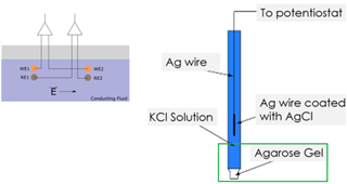
We are working in DC coupled Biopotential recordings. We are currently comparing two different electrode types that are exposed to the same environment at the same time, and should theoretically be giving the same recorded signals back. We are using Instrumentation amplifiers to record these differential signals.
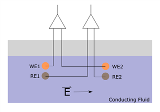
Our circuit design works wonderfully when we are working with only one pair of electrodes and only one INA. Problems arise when the second pair of electrodes is added in here.
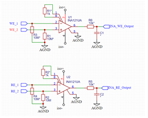
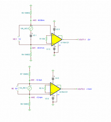
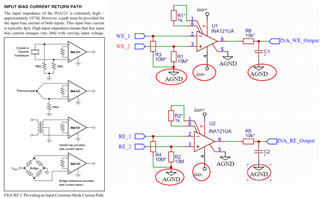
In the above circuit, we have two INA amplifiers which are powered by an isolated DC/DC converter, both relative to the isolated AGND, where the original power (relative to digital GND) comes from an external power supply. The INA outputs head to an ADC on the same isolated power supply. To bias the amplifiers to common mode input, the 10M ohm resistors are added onto the electrode inputs. An asterik in the diagram represents that this component is not necessarily added in. Again, this circuit measures well when only one amplifier is in the solution. As soon as the second is added, we are still able to record signals, but much the inherent value of the signals is compromised due to the 20M ohm resistance connecting WE to RE through the AGND connections. This takes the INA leakage current from the pA scale down to the 100nA scale. The reason for this is that the different metal electrode types each have different Nernst potentials in a biological fluid. The WE electrodes could have a 500-1000 mV DC bias compared to the RE electrodes, thus creating a current flow from WE to RE.
The question is, is it possible to still record with both electrode types and maintain the necessary common mode biasing of the amplifiers? Are there ways to circumvent this?