This thread has been locked.

If you have a related question, please click the "Ask a related question" button in the top right corner. The newly created question will be automatically linked to this question.

OPA2675: How to drive a 100 Ohm Twisted pair with a Max gain and 100MHz bandwidth?

Part Number: OPA2675
Other Parts Discussed in Thread: OPA2677, TINA-TI, THS6222, OPA2673

Hello,

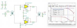
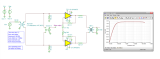
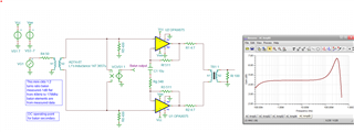
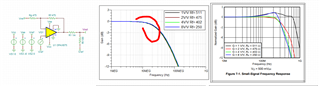
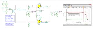
I am going to drive a 100 Ohm twisted pair line. The input p-p voltage is around 100mV and I would like to amplify it am much as possible to keep the 100 MHZ bandwidth. Could you help me to adjust the passive values? I tried to follow the datasheet recomendations but it seems a bit different. I also tried to convert the single input to differential but TIAN gave me errors!

Tahnk you

LineDriver.TSC

  • what frequency range is required?

  • on the minimum low F side?

  • Hi Michael,

    Thank you for your reply. The bandwidth of around 1MHz to 100MHz is required.

  • Incidentally on your TINA file the V+ op amp inputs do not have a DC path for bias current, you need to add R's to ground for that at some ok value - also, normally you are driving the input balun with some source impedence?

  • Hi Michael,

    Thank you for your notes.

    I have revised the design to include a DC path for the V+ inputs. Additionally, I have set the recommended passive values according to the datasheet. However, I have noticed that the bandwidth is significantly lower than anticipated. Could you please advise if there might be any other factors I am overlooking?

    Thank you

    5850.LineDriver.TSC

  • Well 1st of all Mojtabe, we need to get a real balun model in here, the ADT4-6T looks promising, here is its output with a matched secondary 1:2 step up

    Now you don't need to match across a balun and increasing those 200ohm terminations will reduce the insertion loss and shifts the response up in frequency

    here is 499ohm on each side - pretty promising, flat at 1Mhz then peaking a bit at 100Mhz which will equalize the eventual amplfier rolloff - can push its gain up until it is rolled off .5dB at 100Mhz and this will equalize flat to the amp outputs

    So the OPA2675 is a recent addition to a  long line of dual CFA for line drivers - this one has active off line control so aimed and PLC apps for in house wiring comm networks.

    I did open the TINA reference design for the OPA2675, that modelled AC response is way low vs datasheet - that model is apparently way off, can't use it, 

    Try the original DSL line driver with the 2011 model update, the OPA2677 - ok, this is looking pretty good, 22dB gain where I replaced your output balun with just a diff to single sensor, that whole output line model still needs to be added, but the flatness is only 0.7dB down by 100MHz. Work on your load model. There is a whole nuther world of output twisted pair active output impedance things out there too that was used everywhere in DSL, notBalunInputOPA2677.TSC there yet for this question 

  • here is that file in TINA V9 so you can open it, 

    1145.BalunInputOPA2677.TSC

  • Hello Mojtaba,

    Please let us know when you have additional questions.  I am going to review the OPA2675 model and let our team know about potential performance discrepancies. 

    The OPA2677 model, as Michael proposed, should give you an understanding of what to expect in the interim.

    Best,

    Alec

  • Hi Michael,

    Thank you for the provided design. It meets all the requirements.

    Two questions: how did you extract the inductances of the balun (ADT4-6T). I am asking since I could not find them in the datasheet.

    OPA2677 model has an extra pin which is not in its datasheet! is this an enable/power on pin since you connected it to Vcc?

    Thank you

  • Hello Mojtaba, 

    Some of the figures are missing but I think all the important ones are still showing up here, I don't actually do the insertion loss step anymore, messing up too many other things. 

    https://www.planetanalog.com/measuring-modeling-wideband-baluns-for-application-to-adc-input-stages/

  • Hello Mojtaba,

    If you go to your TINA-TI SPICE simulation and either "click" or "double-click" your OPA2677, you can select "Enter Macro" and view the pin assingments in the SPICE model.

    For the OPA2677 SPICE model a Disable pin (DisA) was included.  This is likely due to the DSL & PLC applications of TI's line drivers, which often had disable, shutdown, or two control pin bias modes.  The OPA2677 may have had "disable" functionality at one point, or perhaps the model engineer added the feature.  This can be seen on OPA2673/5 and THS6222, for example.

    Best,

    Alec

  • Thank you, Michael and Alec,

    Your information has been incredibly helpful in resolving the issues and optimizing the circuit. I have one final question: Sometimes, two capacitors are needed in series with the transformer to block the DC, but TINA gives an irregular circuit error. Is there any way to fix this?

    Thank you.

  • Hello Mojtaba,

    TINA has difficulty resolving where the current would go at nodes with AC-coupling capacitors.  Rather than just leave the capacitors out of your simulation, you can try providing a very high resistance path to GND at that node, which will not have a large effect on your circuit but can provide the simulator a way to converge and provide a result.  This is similar to how 1T Farad and 1T Henry capacitors and inductors are used during stability analysis.  You can use a 1T Ohm resistor at the node prior to the two series capacitors.

    Best,

    Alec