This thread has been locked.

If you have a related question, please click the "Ask a related question" button in the top right corner. The newly created question will be automatically linked to this question.

OPA172: Phase jumps when modifying high frequency feedback in Tina-TI (AC analysis)

Part Number: OPA172
Other Parts Discussed in Thread: TINA-TI,

Hello,

using Tina-TI, I'm running AC analysis for this fairly simple circuit. Its *.tsc file is attached below.

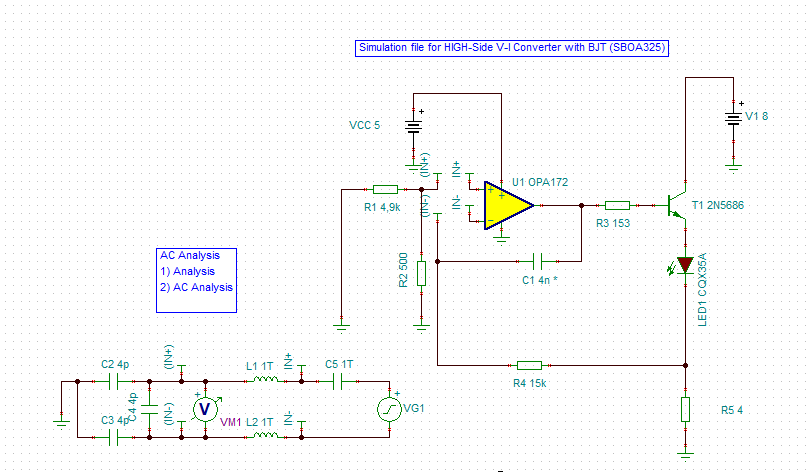
According to application note SBOA325, capacitor C1 provides a high-frequency feedback path that bypasses the transistor T1.

To see the influence of C1, I'm sweeping its value from 3nF to 6nF during AC analysis.

AC analysis shows: When C1 is < 5nF, the phase starts at +180°. For C1 >= 5nF, the phase starts at about -180°. I wonder why this is?

Is this a property of OPA172 or is it just a Tina-TI simulation quirk (e.g., "phase wrapping", as +180° and -180° are basically equivalent)?

Thanks.
Dan

23 TI Forum AC Analyse von 20.TSC

  • Hello Dan,

    It is a TI-Tina quirk. If you flip VG1 or VM1 (not both) upside down then all the curves will keep the phase together. However curves start at 0 degrees then fall to -124 degrees. They are together but you need to add 180 degrees to get the actual phase margin.

    +180 degrees is the same as -180 degrees.