This thread has been locked.
If you have a related question, please click the "Ask a related question" button in the top right corner. The newly created question will be automatically linked to this question.
Tool/software:
Currently designing a radar level gauge product
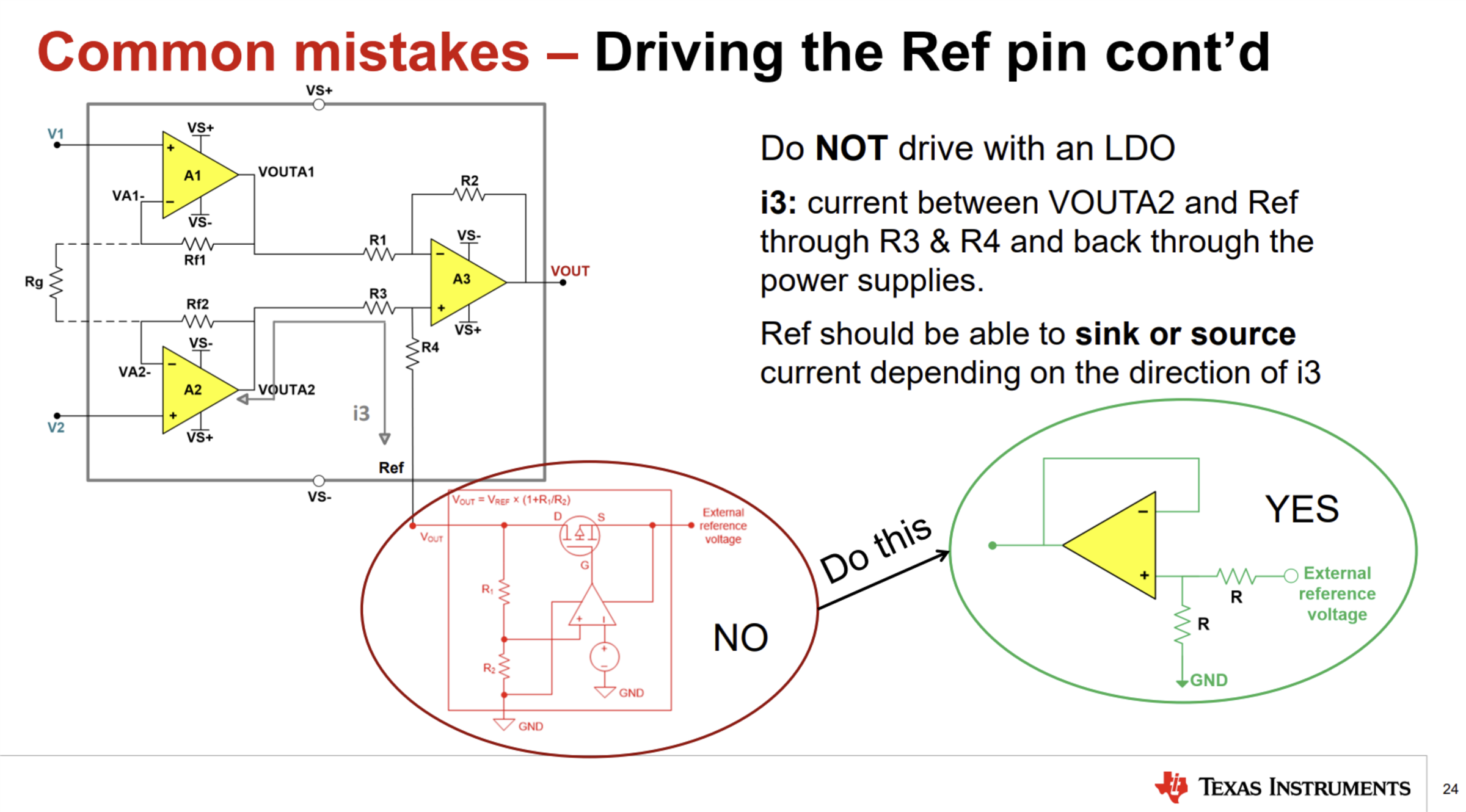
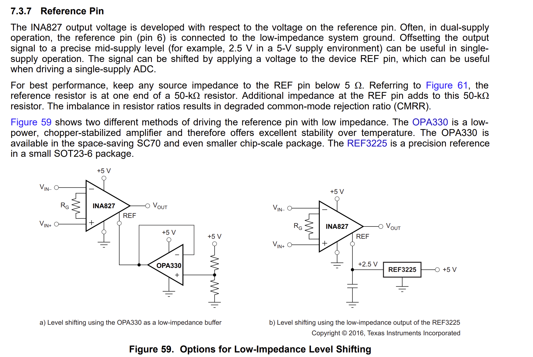
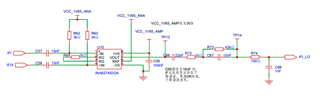
The INA827 circuit was used, as shown in the following figure.
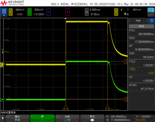
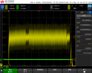
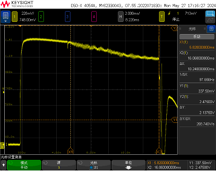
Now debugging has found that its differential frequency signal output value is relatively small,
How to set the parameters of the two-stage RC circuit after the IF signal range of 3K-40K.
How to set the gain to achieve the optimal SNR value.
Thank you for your attention. Thank you
Hey Feng,
Can you show how you are providing the 1.65 V mid supply voltage for both the input pins and the reference pin?
Best Regards,
Chris Featherstone
Hey Chris,
Hello, there was a circuit design error and the power supply PIN voltage has been modified to 3v3 ,VCC_1V65_AMP is now changed to 3V3,The IFI and IFIX signals in the schematic are intermediate frequency signals, with a frequency range of 3k~34kHz. The signals are based on a 1.65V DC level.
Hey Chris,
The following figure shows the waveform of the input signals for IFX and IFIX.
The figure below shows the amplified signal of the IFI channel, indicating that useful signals are difficult to detect and are basically submerged in noise.
Hi Feng,
I see that an LDO is being used to drive the reference pin. We recommend using a buffered amp such as the OPA333 to drive the reference pin.
There is a video series on our TIPL training where the slide below came from. The link can be found here:
https://www.ti.com/video/series/precision-labs/ti-precision-labs-instrumentation-amplifiers.html
I hope this information helps.
Best Regards,
Chris Featherstone