This thread has been locked.
If you have a related question, please click the "Ask a related question" button in the top right corner. The newly created question will be automatically linked to this question.
Tool/software:
Hello TI,
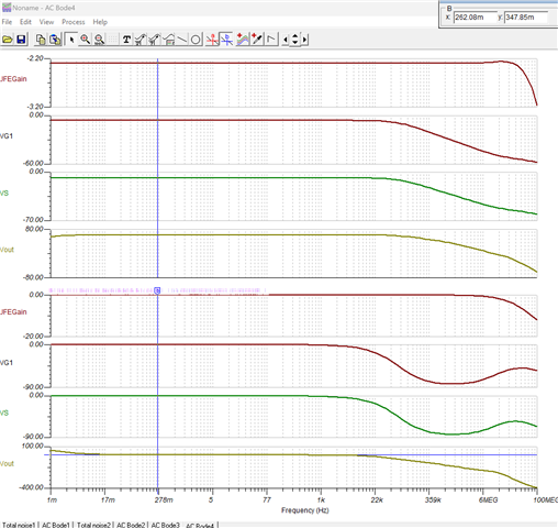
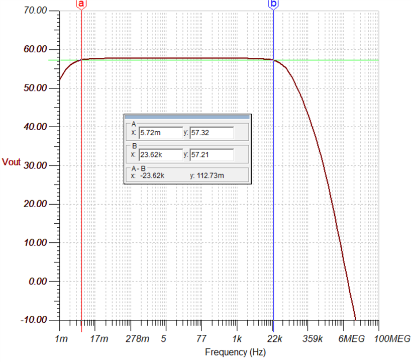
I am running a simulation of piezo disc connected to INA849 amplifier through JFE140, ideally I would like to modify this design with voltage generation as a piezo disc. I made sample schematic of it, but I face issues in AC transfer characteristics. Please have a look at my design as what may be going wrong in it.
Also my noise characteristics is very off, please suggest what is wrong in the simulation result.6332.VoltageMode.TSC
Hi Sumeet,
This seems to be identical to the query in the thread below.
https://e2e.ti.com/support/amplifiers-group/amplifiers/f/amplifiers-forum/1359478/ths7001-ths7001
Best,
Raymond
Hi Sumeet,
I was unable to get your simulation to work. I am unsure why it isn't working. It is missing ground on the ref amp. When I add the ground the DC simulation still doesn't work. I attached my simulation which is essentially the same circuit as yours. This is what I used to write my application brief.
6153.INA849 with JFE Front End With mic source impedance.TSC
I hope this helps.
Best Regards,
Chris Featherstone
Hi Chris,
I ran a simulation on your design, but I see there is good amount of attenuation happening after 17 m, My frequency of interest is 10Hz till 15KHz, can you tell me how I can improve the gain performance?
Please find the ac transfer characteristics curve.
I have attached a 10 dB active filter to your design to filter out any frequency component after 15 kHz.
I am attaching my design, could you please let me know how I can improve the gain at VF1, and also my waveforms are slightly distorted.
1513.INA849 with JFE Front End With mic source impedancewithFilter.TSC
Hi Sumeet,
I ran the simulation that you provided and the transfer function is flat in the frequency band of interest. Please see the Ac transfer function below. Can you show me where you are seeing attenuation in the Vout gain plot for my reference? I see the gain and phase plots you provided. I do not see attenuation in the Vout gain plot you provided.
The filter circuit that is added to the circuit I provided doesn't work because the supply voltage is a single supply of 5V. The minimum supply voltage of the OPA445 is +/-10V or 20V single supply.
Best Regards,
Chris Featherstone
Hello Chris,
I have been able to make it work, but since INA is part of larger signal chain, I request you to give me an email where I can get support on larger signal chain simulation, as I cannot attach the .tsc file to this thread because of IP issues. My concern is I get convergence and irregular circuit error when I try to do a transient analysis.
Hi Sumeet,
I am glad it is now working. I sent a friend request on the E2E. If you accept the request you may privately message me your email.
Best Regards,
Chris Featherstone