This thread has been locked.

If you have a related question, please click the "Ask a related question" button in the top right corner. The newly created question will be automatically linked to this question.

OPA855: How to make the transimpedance gain lower with opa855

Part Number: OPA855

Tool/software:

Hello, I made a transimpedance amplifier with opa855.

I use the fast laser pulse(edge time is 1.5ns) and avalanche photodiode(rise time 0.6ns).

So, I have a problem associated with stability.

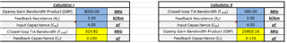
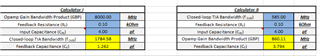
opa855 is stable with almost 3kohm transimpedance gain or larger.

But I want to design 100ohm transimpedance gain with high bandwidth for fast pulse.

I read some transimpedance amplifier's stability documents, like SBOA055A , SBOA122,  else...

According them, I need to 0.3pF capacitor for 100ohm transimpedance gain with opa855. (Total input capacitance is Cpd+Camp=1.2pF+0.6pF=1.8pF)

But my transimpedance amplifier circuit still oscillates.

What can I try to reduce oscillating and stabilize transimpedance ampflier with 100ohm transimpedance gain.

  • Hello,

      Thank you for reading our transimpedance amplifier stability documents!

      You are correct that we advise making the feedback capacitance calculations with the total input capacitance in mind. We have a TIA calculator that will do this calculation for you based on these documents. The calculator calculates the necessary CF, or feedback capacitance, with a phase margin of 65 degrees or a Butterworth response with a quality factor of 0.707 (maximally flat passband frequency response). Therefore, you can push the limits a bit on these calculations to a min stability of around 45 degrees, where you would see some peaking in the frequency response or overshoot in transient response.

      Here is the calculations with 3kOhm transimpedance gain that is stable in your tests: 

      I am using Cin of 4pF which is 1.2pF (PD cap) + 0.6pF (common-mode amp cap) + 0.2pF (diff amp cap) + 2pF (estimated PCB cap). You would have to estimate your PCB capacitance which will depend on your PCB stackup, usually this would be an extra 1-2pF.

      Here is the calculations with 100Ohm transimpedance gain: 

      Calculator I calculates based on the GBP of the amplifier, while Calculator II calculates based on your closed-loop bandwidth which I calculated based on your rise time of the PD that your provided. 

      The 3kOhm transimpedance gain is probably stable since CF needed is very low which is added on from parasitic of the PCB and feedback resistor. For a 100Ohm transimpedance gain, try adding a feedback capacitance between 1.5pF to 4pF. 

      You can find the TIA calculator here: e2e.ti.com/.../faq-transimpedance-amplifier-calculator

    Thank you,

    Sima