Tool/software:
Dear Engineers,
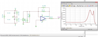
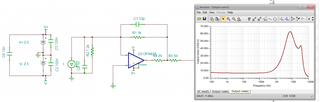
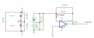
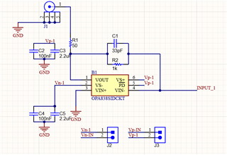
I have designed a transimpedance amplifier as follows:
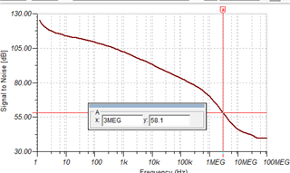
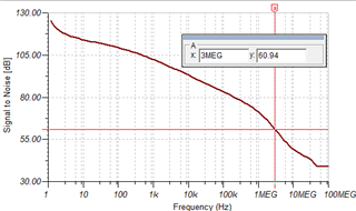
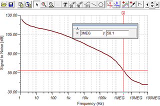
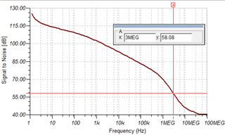
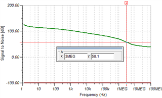
Based on the simulation, I should get around 58 dB for SNR @3MHz:
But what I achieved in my experimental results is as follows:
-Supply voltage +/- 1.5 V
-Power consumption 900 uA (datasheet=950 uA)
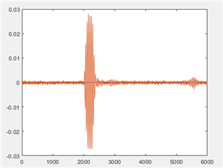
Output signal:
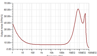
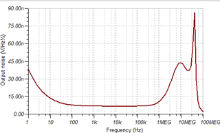
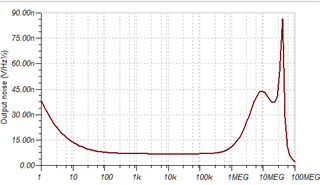
Noise:
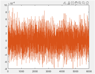
Calculations:
-〖Signal〗_RMS= 3.8 mV
-〖Noise〗_RMS= 0.25 mv
-SNR (MATLAB)= 23.4 dB (I used snr() function in MATLAB to calculate the SNR)
-SNR (Calculated)= 20log(〖Signal〗_RMS/ 〖Noise〗_RMS)= 23.6 dB (calculation by hand)
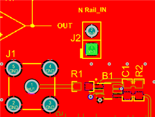
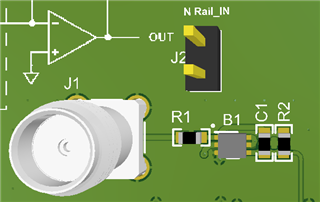
PCB and schematic details:
So, the achieved SNR is 23.4 dB, but what should I get based on simulation is totally different 58 dB, would you please let me know why there is this much difference in the experimental and simulation results?
Best regards,