This thread has been locked.

If you have a related question, please click the "Ask a related question" button in the top right corner. The newly created question will be automatically linked to this question.

PGA855EVM: Gain not working

Part Number: PGA855EVM
Other Parts Discussed in Thread: PGA855

Tool/software:

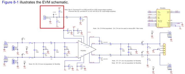
I just purchased the PGA8555EVM board.  It looks like my version is E1.  Manual shows errata notes for E2 but nothing for E1.  Not sure why I got shipped (from Mouser) a EVM that is at least 3 revs behind. Problem is gain not working correctly.  

  • Hello Daniel,

    Regarding the PGA855EVM revision:

    The only revision on the PGA855EVM involves the VOCM voltage divider connections through resistors R1 and R3.

    Rev A connects the VOCM voltage divider resistors R1 and R3 to the LVDD+ and LVSS– (output-stage supplies) as shown below. 

    Previous Rev E1, E2 (these are identical) connected the VOCM resistor divider R1 to VS+, and R3 to VS- (input stage supplies). 

    When using rev E, if the application uses a different voltage on the input stage supply (VS+,VS-) and output stage supply (LVDD+, LVSS-), the user will need to drive the VOCM pin through test point (TP1) or connector (J1) to the required VOCM voltage. Alternatively, one could remove R1 and R3 resistors, and the VOCM pin will default to the middle of LVDD+, LVSS- supplies through a weak internal voltage divider (500kΩ - 500kΩ) inside the PGA855 device. Most applications drive the VOCM pin to the required voltage, so typically this is not an issue.  

    Regarding the issue with the PGA gain:

    To help determine if the issue is related to the EVM, and help debug the issue, please provide the following information:

    1) Please provide the voltage potential on the input stage supplies (VS+,VS-), the output stage supplies (LVDD+, LVSS–) and VOCM voltage.

    2) Details of the input signal:

    Input common mode voltage average voltage of the inputs: {(IN+) + (IN-)} / 2

    Differential voltage amplitude, difference between IN+ and IN-

    Signal frequency

    3) PGA Gain where the issue occurs

    One of the most frequent problems involving instrumentation amplifiers, occur when the device is operated outside its specified input common-mode linear range or differential voltage range. Regarding the input voltage range on the PGA855, the voltage at either input (IN+ or IN-) requires a headroom voltage of at least 2.5 V (or larger headroom) from the positive and negative rail. The PGA855 is similar to standard instrumentation amplifiers. Each amplifier inside the PGA has it’s own input and output swing limitations and this will be affected by the PGA Gain, supplies, VOCM voltage conditions and input-common mode.   These limitations combine into an overall input differential and common mode voltage versus output swing range limitations. The PGA855 data sheet section 9.1.1 on p. 24 provides an explanation, and plots 9-1 to 9-4 shows the general behavior for a few different supply and gain conditions. Because this relationship can be complex, we offer an excel calculator, to verify the device is inside the input/output linear range, see below:

    https://www.ti.com/tool/download/PGA85X-INPUT-OUTPUT-RANGE-DESIGN-CALC

    The attached pdf file offers a brief explanation to use the calculator:

    PGA855-Input-and-Output-Range-Calculator_instructions.pdf

    Once we get some more info, then we can proceed, and certainly help address if this is a EVM issue.

    Thank you and Regards,

    Luis 


  • Hello Daniel,

    I have not heard back from you,  If you still are experiencing issues, please feel free to post.

    Thank you and Regards,

    Luis