Other Parts Discussed in Thread: INA351
Tool/software:
Hi E2E
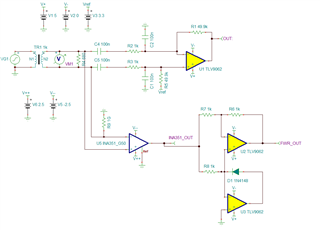
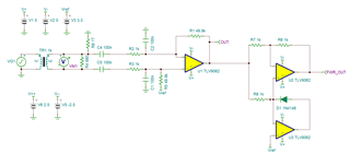
I am using TLV9056 as a differential amplifier to amplify the output from the current transformer (1:1000) of input frequency of 50Hz, this is to measure the line currents and the noninverting pin is biased with 3.3V.
Below is the reference schematic for that
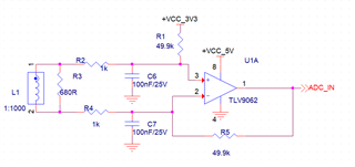
and the above circuit is working as expected as per design.
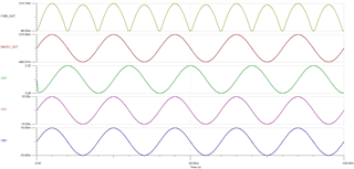
I also want to repurpose the same CT output for some different applications for which I need to convert the same CT output into pulsating DC, I am referring to TI Application note sboa296 , I need design suggestions on how can I use the same CT output for two different circuits which are having two different biasing.
So conclude my requirements, I want to use the CT output for two applications
1. Differential amplifier biasing with 3.3V voltage
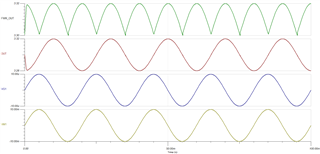
2. Pulsating DC output from CT with a certain gain.
Please let me know if you need any other information.
Regards
Chaitanya


