LM675: AC sine wave voltage to current source for coil / inductor

Part Number: LM675
Other Parts Discussed in Thread: ALM2402F-Q1, ALM2402-Q1, ALM2403-Q1, OPA593, OPA564, TINA-TI, OPA564-Q1

Tool/software:

Hello.

I'm beginning a project that is a little different for me.

I will show the details I can.

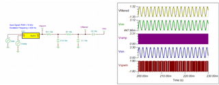
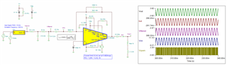
Input: maximum 1Vpp (+500mV peak, -500mV peak) AC sine voltage wave, frequency 6Hz to 620Hz.

Output: 5mA per each 1mV at the input, the load is a coil, the inductance will be something between 1mH and 2.2mH, 2.2mH more probably.

When Vin instantaneous is +500mV, the instantaneous current on the coil is 2500mA, and when Vin instantaneous is -500mV, the instantaneous current at the coil is also 2500mA, but with the current flowing in the opposite direction (AC). Iout / Vin has a relation of 5 (5mA/mV), but the relation also can be between 4.5 and 5.

Without DC current offset on the coil, if possible.

It's a voltage to current converter, but it's AC.

The purpose is to apply a sine current in the coil for the generation of adjustable amplitude/frequency electromagnetic fields in the frequency range of 6Hz to 620Hz, although the coil was not chosen yet, probably it will have a custom design. I can't go far in the explanation due to the NDA of the project.

I would like to know if Texas Instruments has some documents related to this, that could help on this. Or if some related material can be recommended. And yes, I'm looking for circuits that can make this, perhaps using a power operational amplifier like the LM675.

Regards.

  • Hi Jeferson,

    When Vin instantaneous is +500mV, the instantaneous current on the coil is 2500mA, and when Vin instantaneous is -500mV, the instantaneous current at the coil is also 2500mA, but with the current flowing in the opposite direction (AC). Iout / Vin has a relation of 5 (5mA/mV), but the relation also can be between 4.5 and 5.

    When the application is driving inductive load, you do not want to apply step function at input. 

    Let us say L = 1mH, and V = 0.5V, the di/dt = V/L = 0.5V/1.0mH = 500 A/sec. Of course, the op amp in unable to deliver this rate of current, thus output distortion will occur. The R &L time constant will dominated at the output. You should use sinusoidal waveform to drive the inductive load, and avoid sudden di/d change at the output. 

    Without DC current offset on the coil, if possible.

    You may use capacitive coupling to interface with the inductive coil. 

    Output: 5mA per each 1mV at the input, the load is a coil, the inductance will be something between 1mH and 2.2mH, 2.2mH more probably.

    Can the coil be driven in floating manner? In other words, it is driven differentially at the output. What is the maximum output volage swing for the application. 

    We have other op amp, such as ALM2402-Q1/ALM2402F-Q1/ALM2403-Q1, OPA593, OPA564  and other power amplifiers depending on the driving requirements. 

    Enclosed is a resolver application note, which it may be similar to what you are trying to do. 

    https://www.ti.com/lit/ab/sboa504/sboa504.pdf?ts=1719948544776&ref_url=https%253A%252F%252Fwww.ti.com%252Fproduct%252FALM2403-Q1%253Futm_source%253Dgoogle%2526utm_medium%253Dcpc%2526utm_campaign%253Dasc-null-null-GPN_EN-cpc-pf-google-wwe%2526utm_content%253DALM2403-Q1%2526ds_k%253DALM2403-Q1+Datasheet%2526DCM%253Dyes%2526gad_source%253D1%2526gclid%253DEAIaIQobChMIgr7jxIuJhwMV-drCBB2TtA4jEAAYASAAEgJu-PD_BwE%2526gclsrc%253Daw.ds

    If you have other questions, please let me know. 

    Best,

    Raymond

  • Hello Raymond.

    Thank you very much.

    I don't have all answers yet.

    The OPA564 is interesting. We can reduce the 2500mA of the original post to 1500mA also, because the output of the OPA564 is for up to 1.5A.

    The idea is to have in the circuit, an IC which is a function generator (until now is planned a DDS - Direct Digital Synthesis), which will generate only sinusoidal voltage waves (0.61Vpp fixed), with frequency range of 6Hz to 620Hz, and this IC generates a fixed output amplitude as far as I know (0.61Vpp fixed), and the amplitude can be reduced with the use of a digital potentiometer, and the DC offset can be removed with a capacitor. Then at this point comes the circuit pretended by this topic, to convert the sinusoidal voltage wave to a current wave that will flow through the coil.

    Maybe it can be implemented in a easier way. The basic idea is that there will be a coil, in which we wanted to apply a sinusoidal current (with adjustable amplitude), for the frequency range of 6Hz to 620Hz (adjustable).

    Regards.

  • Hi Jeferson, 

    The idea is to have in the circuit, an IC which is a function generator (until now is planned a DDS - Direct Digital Synthesis), which will generate only sinusoidal voltage waves (1Vpp fixed), with frequency range of 6Hz to 620Hz

    Are you referring to complementary SPWM input signal, and go through the filter and obtain the sinusoidal input?

    620Hz SPWM Sinusoidal Input 07022024.TSC

    If you can provide the input and output swing, I can simulate this for you. 

    Best,

    Raymond

  • Hi Jeferson, 

    Here is a driving example and we can fine tune the inductive load accordingly. If the excitation frequency can be programmable accordingly (to avoid sudden change in di/dt at the inductor), the inductive coil should not be induced in high spike voltage at the output, and transition should be smooth.   

    SPWM Sim Drivng 2.2mH coil 07052023.TSC

    Please let me know if you have other questions. 

    Best,

    Raymond

  • Hi Raymond.

    Thank you.

    The IC that I mentioned which is a DDS (Direct Digital Synthesis) is this one:

    https://www.analog.com/media/en/technical-documentation/data-sheets/AD9837.PDF

    In the datasheet, on page 3, is shown:

    It has a SPI interface to set the output frequency and shape (square, triangular, sinusoidal), but the output amplitude seems to be a fixed value, with 0.61Vpp.

    In the first page is shown that the output comes from a DAC:

    I have not tested this chip yet, but also I believe that if the output comes from a DAC, that the output waveform this chip generates probably will present small voltage steps, because this DDS chip have a 10-bit DAC, there are DDS chips with 12/14/16 bit DAC, but they are too expensive. This DDS IC with 10-bit DAC of the link above have smaller cost. Because actually we will have 3 coils in the project, 3 times the same driving circuit, 3 times the same waveform generation circuit.

    Does Texas Instruments have any IC which is a function/waveform generator?

    The idea based on this DDS chip, was:

    MCU (SPI interface) ---> DDS IC (sinusoidal voltage wave output, 0.61Vpp fixed, configured through SPI to output a frequency between 6Hz and 620Hz, I think it can present a smooth transition...) ---> Digital Potentiometer (voltage amplitude control) ---> Buffer or Amplifier with OpAmp ---> Capacitor (remove DC offset) ---> Circuit to convert voltage to (AC) current which flows through the coil. Something like that.

    What is this simulation software that you are using? Could I install it and open your simulations on it?

    Regards.

  • Hi Jeferson, 

    Does Texas Instruments have any IC which is a function/waveform generator?

    Enclosed is our DAC waveform generator, if you are interested our product. We have many DAC IC. Using DAC to generate sinusoidal waveform will be easier than SPWM method. You may want to keep out the harmonic noises outside of the operating frequency range.  

    If you send an E2E query about the DAC, the team will be able to help you to find the best option for your application. 

    https://www.ti.com/lit/an/slaae66/slaae66.pdf?ts=1720022280215&ref_url=https%253A%252F%252Fwww.google.com%252F

    https://www.ti.com/data-converters/dac-circuit/products.html

    https://www.ti.com/video/series/precision-labs/ti-precision-labs-digital-to-analog-converters--dacs-.html

    What is this simulation software that you are using? Could I install it and open your simulations on it?

    I am using Tina-TI simulator, which you are able to download directly from the link below (free). I can even show you how to simulate the power dissipation on the driver once you are familiar with the tool.  

    https://www.ti.com/tool/TINA-TI

    With the previous enclosed simulation, you can replace the SPW input stage with a voltage source at 0.61Vpp from 6Hz to 620Hz. 

    At OPA564-Q1's output simulation, I am using CL high pass filter to block DC components. Since you input signal is low down to 6Hz, the AC coupling requires large caps, the pole should be configured at 0.6Hz or lower (try to avoid the Q from CL circuit), if you want to block DC signal. 

    You may also consider to drive a transformer differentially, and use the transformer's secondary to drive the inductive coil. Nice about the configuration is that you power efficiency will be doubled, and you may use lower supply rails to power larger amplitude inductive load. Or you can drive the coil differentially and directly as well.

    If you have other questions, please let me know. 

    Best,

    Raymond