This thread has been locked.

If you have a related question, please click the "Ask a related question" button in the top right corner. The newly created question will be automatically linked to this question.

OPA855: Self-excited oscillation occurs in the TIA circuit by OPA855, please help, thanks.

Part Number: OPA855

Tool/software:

Hi,

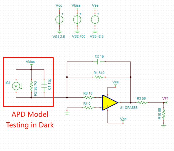
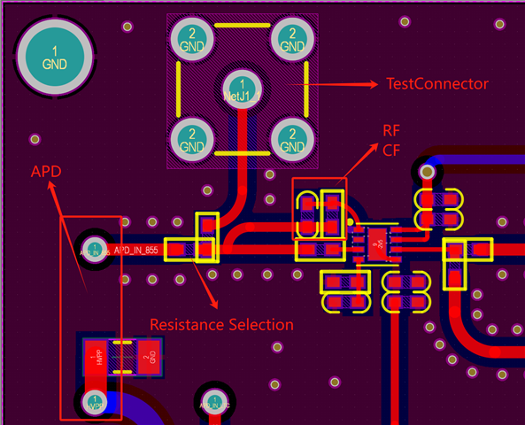
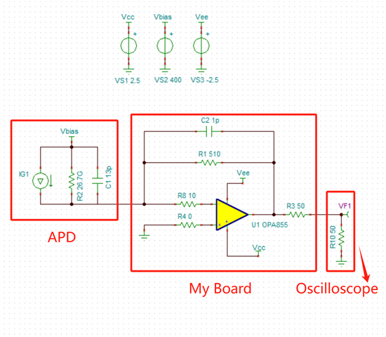
I am debugging a TIA circuit, it's a single stage amplifier by OPA855, there are schematic and PCB layout as below:

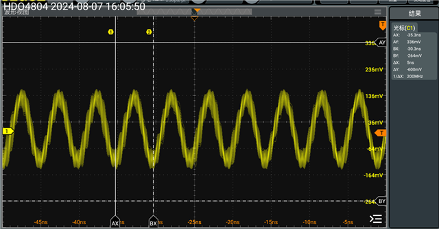
The circuit outputs a high frequency oscillating waveform when testing in dark environment, the oscillating frequency is about 200MHz.

This problem bothered me for a long time, please help me find the reason, thanks very much!

  • Hi,

    I was able to run a stability simulation with the given photodiode capacitance and feedback components and it did not show any concerns with the circuits phase margin. I was wondering if you could share how you are capturing the signal you are seeing. Are you probing the output of the device or is this going into a 50ohm terminated scope? We have seen issues with using a probe, so I would like to rule out this as a potential issue.

    Best Regards,

    Ignacio

  • Hi,

    Let me try to describe my testing environment:

    My board contains the High-Voltage power supply module(about 400V), a positive and negative power supply module(±2.5V), the amplifier module(OPA855) and an APD interface.

    The oscillating waveform is measured on an oscilloscope. The oscillating waveform is measured on an oscilloscope, whether the load is 50 ohm or 1 megohm, the waveform will be measured. There is only a difference in magnitude

  • Hi,

    Thank you for clarifying the setup. Like was mentioned the simulation showed no phase margin concerns however this is with a model, which does not capture a real-world configuration perfectly. Do you see a change in result when you adjust the feedback capacitor up and down from the 1pF? I would also suggest removing the R8 10ohm resistor with a short and see if this makes a difference. We do highlight this in the datasheet however we have found in certain customer circuits being a problem with regards to stability. The last question I have is regarding the decoupling capacitors, it looks like the layout had some properly laid out but if you stack some decoupling capacitors on top of the ones in place do you see a difference at the output? This is likely not the cause, but we have also seen this in rare occasions as well.

    Best Regards,

    Ignacio