This thread has been locked.

If you have a related question, please click the "Ask a related question" button in the top right corner. The newly created question will be automatically linked to this question.

XTR111: 4 to 20 mA output

Part Number: XTR111

Tool/software:

Hi,

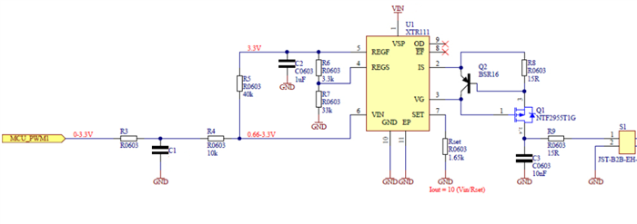
My controller don't  have DAC i am using a PWM output for the 4 to 20 mA output, Now i want to use XTR111 for the 4 to 20 mA.

So is it possible without DAC using PWM may I generate 4 to 20 mA using XTR111 ? 

If you have document pls provide.

  • A PWM DAC is a DAC.

    You can use a PWM signal for the XTR111, as long as you use a low-pass filter to convert the signal into an analog signal.

    Designing high-performance PWM DACs for field transmitters shows an example, but it is probably more complex than you want.

  • Hi Purvik,

    Below is just quick example of the XTR111 when using a PWM input signal for a 4mA to 20mA output. 

    If the PWM signal output signal is 0V-3.3V from the MCU, one possible circuit would be to set your Regulator voltage to 3.3V, by adjusting the XTR111 voltage regulator resistors R7=10.1kOhm and R6=1.01kOhm resistors as shown below. Set the RSET resistor to 1.65kOhm, this will allow you to obtain a 20mA output for max input voltage of 3.3V. Use a voltage divider at the XTR111 input using R5 = 40kOhm and R4=10kOhm to scale the input voltage. 

    The MCU PWM output connects through a passive filter into the XTR111 voltage divider.

    Please note, the RC filter will need to be designed and tuned per your ripple tolerance and PWM frequency requirements.

    Attached is an application note that discusses how to design filters for a PWM application according to the maximum ripple that may be tolerable on your application. The application tunes the filter for a 12-bit resolution application, but the method could be used for different voltage resolution or ripple requirements. 

    TI Precision Designs: Verified Design Microcontroller PWM to 12bit Analog Out:

    https://www.ti.com/lit/ug/tidu027/tidu027.pdf

    Thank you and Regards,

    Luis

  • Hi,

    My PWM output is 16 bit and voltage is 0 to 3.3V.

    Please help me to provide RC filter design for my requirement.

    Is it require Post Filter Amplifier for Ripple Verification ?

  • HI Purvik,

    The post filter ac coupled amplifier circuit is only used to measure/test the ripple of the PWM on the application note, but it is not strictly required on the XTR111 circuit above. 

    Nevertheless, a buffer amplifier could be added at the RC filter output to isolate the loading of the XTR111 input voltage divider. The PWM output is 16 bit, and voltage amplitude is 0 to 3.3V. What is the frequency of the PWM? This will help set the RC corner filter frequency 

    Keep in mind, the absolute accuracy of the circuit will be also a function of the accuracy of the amplitude of the PWM train. The RC filter order only helps to attenuate the noise/ripple.

    Thank you and Kind Regards,

    Luis  

  • pls find the attached schematic is it OK ?

    Here my PWM Freq is 122 Hz and 16 bit output and voltage is 0 to 5 VDC, Please confirm RC circuit values are okay ?

    I have implemented this circuit and tested i am facing an issue values are fluctuating, Like i have a set 20.00000 mA it's jumping to 20.00050 or 19.99835 (This is just example). This is jumping continuously but it's happen.

    One more issue is if i have set 20.00000 mA at 60000 count of PWM when i change count of PWM like 60010 that time output will not change when change like 60050 that time output will change, so pls advice how to resolve this, because my resolution is lost.

  • HI Purvik,

    Why is the frequency of the PWM only 122Hz?  Is it possible to use a higher frequency PWM? This will make it easier to filter the ripple.If you are using a 122Hz PWM with the second order filter above, the expected ripple noise is 30mVpk at the input of the XTR111; which will be gained up by the XTR111 and converted into current. If you require higher resolution you will need a higher order RC filter.


    Please also keep in mind that the XTR111 voltage to current transmitter targets applications with current ranges of 0mA–20mA, 4mA–20mA, 5mA–25mA with DC precision. The XTR111 accuracy relies on a self correction algorithm involving the dynamic matching of internal current sources. Therefore, the XTR111 may require 100µs complete correction cycle, and Figure 39 of the datasheet shows the XTR111 inherent ripple generated from the individual current source values that average to the DC value over the full-cycle.  The XTR111 inherent output glitch is proportional to the output current level and scales with the resistor load value.  Additional filtering at the XTR111 output can be used to reduce the glitch, as shown of Figure 39 and Figure 40 of the XTR111 data sheet. Please review the Dynamic Performance section on page 15.

    What current output range and current resolution do you require?  What is your peak-to-peak current noise target?

    Thank you and Regards,

    Luis 

  • My current range is 4 to 20 mA and i want resolution of 0.001 mA, Is it possible ?

  • As per my knowledge if i will increase freqn i will loose my step resolution of duty cycle my timer is 16 bit only.

  • HI Purvik,

    If we look at the XTR111 data sheet Figure 40, this shows the noise performance at the output of the XTR111 (XTR stand alone) after using an output RC low pass filter of 10kΩ and 10nF. Please note, this accounts for the ripple noise inherent to the XTR111 stand-alone, when using a very low noise input signal. Looking at the plot, the noise is about ±5mV on a 500Ω load; or a current noise of about ±0.010mA after using a 10kΩ and 10nF low pass filter at the XTR111 output. 

    Your application targets a noise of ±0.001mA, hence realistically you would need to use a discrete current transmitter design such as the one documented in the simulation below at the bottom of this post.

     The frequency of the PWM is low, at  122Hz, hence, you will need a 5th order low-pass filter with a corner frequency around 12Hz to eliminate the ripple. You will need relatively large capacitors (use C0G grade capacitors for good stability over frequency and low dielectric absorption). I don't believe you will easily achieve the level of noise performance you seek with the PWM approach, and there are other accuracy errors/limitations with the PWM approach.

    Since you require a very low noise ±0.001mA on the circuit on a 20mA full-scale, you may consider using a low-noise, high precision, 16-bit discrete DAC, and the op-amp and FET discrete design shown below. 

    0777.OPA2197_current_transmitter_forum_10-7-21.zip

    The method to design this circuit is documented on the application note below.  I only modified the circuit for a higher voltage amplifier and to provide the 0-25mA output for an input signal of 0-5V. The resistor components can be scaled per your voltage input and current output requirements.

    Verified Design High-Side Voltage-to-Current (V-I) Converter

    Thank you and Regards,

    Luis

  • Hi,

    Pls find the attached picture this is my final circuit, Here i want to required stable data 0.01 mA minimum, But i am facing an issue while i have set 20.00 mA output some time values go to 19.97 or 19.98 and come back to 20.00.

    My PWM freq is 1000 KHz. and XTR111 supply is 12 VDC. Pls advice how to resolve it ?

  • Hello Purvik,

    The post above mentions that you have attached an updated schematic; however, there is no attachment on the post. 

    Please re-post the updated schematic,

    Thank you and Regards,

    Luis

  • Hi,

    Pls find the attached picture this is my final circuit, Here i want to required stable data 0.01 mA minimum, But i am facing an issue while i have set 20.00 mA output some time values go to 19.97 or 19.98 and come back to 20.00.

    My PWM freq is 1000 KHz. and XTR111 supply is 12 VDC. Pls advice how to resolve it ?

  • Hi,

    please find the attached schematic and video file for better understanding.

    UTR_V1.1.pdf

  • HI Patel,

    Please take a look at the XTR111 data sheet Figure 41. After using a 10kΩ and 10nF low pass filter (corner frequency 1.5kHz) at the XTR111 output. The ripple noise inherent to the XTR111 device, when using a very low noise input signal, is about ±5mV on a 500Ω load; or a current noise of about ±0.010mA typical. 

    You will need to add a similar low-pass filter at the output of the XTR111.

    Standard X5R/X7R surface mount ceramic capacitors exhibit effects of dielectric absorption. Dielectric absorption is the name given to the effect by which a capacitor, that has been charged for a long time, discharges/recharges only incompletely when briefly charged/discharged. The dielectric absorption effect in the capacitor can also cause some level of instability on the measured output.  Among ceramic surface-mount capacitors, C0G (NP0) ceramic capacitors provide the best capacitance precision. The type of dielectric used in C0G (NP0) ceramic capacitors provides the most stable electrical properties over voltage, frequency, and temperature changes, and have a much smaller dielectric absorption. Therefore, if using ceramic capacitors on the filters, ensure to use high-grade C0G (NP0) capacitors. 

    Thank you and Regards,

    Luis 

  • HI,

    Please find the attached schematic file and confirm is it OK filter circuit ?

    R46 Need to solder ? 

    R46 = 500 Ohm

    4431.UTR_V1.1.pdf

  • Hi Purvik,

    As explained on the post above, if using ceramic surface mount capacitors on the filters, these need to be high-grade C0G/NP0. 

    I notice that you choose to use large 1µF and 10µF capacitors on your input and output filters.  What type of capacitors are these?

    Best Regards,

    Luis

  • Hi Luis,

    This is a ceramic capacitors.

    2 days ago i had tried with 10K and 10nF capacitor but that time output is not changed continuously output shows 5 to 6 mA.


  • What grade of capacitors are these?

  • I am using ceramic type MLCC capacitor 1206 PKG, But I don't have an idea it is what type of capacitor

  • Do you think is it a power supply issue ?

  • HI Purvik,

    One recommendation is to use three oscilloscope probes, and measure the input, output and supply to see if you can identify the source of noise.  Since the noise signal is quite small, it will be challenging to see the noise in the oscilloscope, unless you have an active, or high resolution probe. Attached is a short pdf file explaining oscilloscope placement.

    Making Accurate Oscilloscope Measurements for Noise, Switching, and High Frequency Signals.pdf

    Also, I strongly recommend the use of high grade C0G/NP0 applications in high-performance, precision filtering applications such as this one. These high-grade C0G/NP0 capacitors are available on capacitance values up to 100nF on 1206 footprint (or around ~25nF on 0805 footprint) and offer very low dielectric absorption, providing the most stable results. Lower grade X7R/X5R grade capacitors may exhibit dielectric absorption, resulting in random and/or much longer than expected settling times. The dielectric absorption can manifest itself and show up at the output of the circuit, as very small-level, random/unpredictable offsets riding on top of the DC signal,  where the output of the circuit moves slightly, as you are applying the pulse signal into the input filter circuit.

    Thank you and Best Regards,

    Luis 

  • Hi,

    I have NPO grade capacitors i have used 10K and 100 NF capacitor at output for filter but OP is fixed at 1.007 mA, Output dose not change according to PWM, Then i have replace 10K to 1K that time output is changed but maximum Output is 10 mA. Then I have changed 1K to 100 ohm now same problem accured, Please advice how to resolved it ?