Tool/software:
Hello Dear All,
I got short-circuit with this circuit, and I can not see the problem. Can you look at this? When I remove R119 or R71 everything is okay.

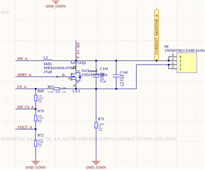
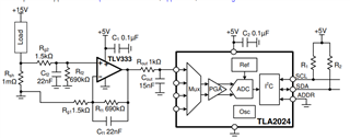
CURRENT_MONITOR_A is LED's positive side.
This thread has been locked.
If you have a related question, please click the "Ask a related question" button in the top right corner. The newly created question will be automatically linked to this question.
TLV333: TLV333: Low-Side Current Shunt Op-Amp Circuit to Single-Ended ADC for Cost-Optimized Monitor
Tool/software:
Hello Dear All,
I got short-circuit with this circuit, and I can not see the problem. Can you look at this? When I remove R119 or R71 everything is okay.


CURRENT_MONITOR_A is LED's positive side.
Oben,
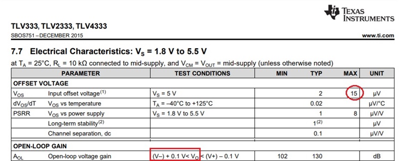
It is possible that you could push TLV333 to short circuit condition - at 25C on 5V supply it can source 5mA while on 1.8V supply only 3mA (see below).
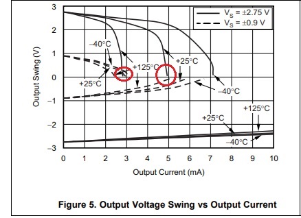
Having said that, your circuit flows in the space - it does not show supply and input voltage at Current Monitor A node. Also, you do not specify what max/min current levels you are trying to measure. If you need further help, please provide full schematic and detailed info of your application.
Marek,
I sended to you friendship for detailed schematic docs, if you accept that I can send you.
Let me explain detailed for you,
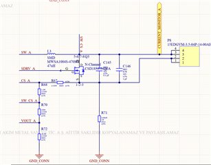
This is my led's output circuit. Positive terminals is P8's 3th and 4th pins, and negatives 1th and 2th. I don't connect my load(led pcb) to P8 and,
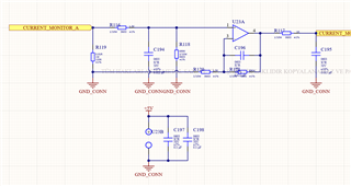
this is CURRENT_MONITOR_A from output on P8 is coming here. There is no load there is no power but short circuit on main power and gnd_conn, but if I removed shunt resistor which 0.01R (R119) or R71 there is no short circuit.
It's difficult to follow your description "there is no load there is no power but short circuit on main power and gnd_conn." I also do not understand what you mean by saying that "there is a shirt circuit." R119 is a shunt resistor across which you measure the current so you cannot remove it.
All in all, I would say following: unlike example in datasheet shown in your original post using gain of G=690k/1.5k = 460, your circuit gain is: G=690k/603 = ~1,144. This means that in order to prevent a non-linear operation of the output stage, there must be some minimum shunt current to drive the output to 100mV or more above ground. Since the max negative offset can be -15uV, the minimum shunt current must be:
Ishunt > [(100mV/1,144)+15uV]/0.01ohm = [87.4uV+15uV]/0.01ohm
Thus, Ishunt > 10.2mA. In order to assure Vout linear operation, do you apply a minimum 10.2mA shunt current when you make your measurement? If not, your measurement may be invalid.
I think you are not looking or want to unterstand what I wrote. There is no difficult to follow my description. I am saying there is no power on my circuit you are still sharing electrical characteristics things, and you did not understand "there is a shirt circuit." just think about it what I want to say here. Also, my gain is not1,144. You are saying it's 603. Marek it's package of resistor that's why 0603 wroten in sch pictures. Please look at my sch pic carefully.
Anyway, short circiut problem.pdf
I added one pdf in attach, please look at it.
Let me explain to you again, When you examine the schematic, there is a load between 28V 1A and 3A coming from the SW_A Net. The "15EDGVM-3.5-04P-14-00AH" connector is the connector to which my LED luminaire is connected. The "CURRENT_MONITOR_A" port connection is the TLV333IDCKR circuit that I installed because I wanted to monitor the current passing through here.
The circuit lies in front of me, laid out on a PCB board. I did not apply any power to the circuit. When I check for short circuit with the help of a multimeter, there is a short circuit between SW_A and GND_CONN. I don't know where this short circuit comes from, that's the question I'm asking you. When I remove R119 or 0.082R here, this problem disappears.
Oben,
Looking at your schematic, what do you see between SW_A and GND_CONN nodes? I see an inductor, L3 (in case you don’t remember, ZL=jwL and thus for DC reading inductor is a short) connecting to CURRENT_ MONITOR_A node and on to 0.01ohm R119 connected to GND_CONN. So if you check for short with multimeter between SW_A and GND_CONN, you should read 0.01 ohm (virtually a short). What is it that you expect to read here and if something different please tell us why?
Oben,
Marek is on travel and will not return for two weeks, so I will help support your question. Sorry for the change and also delay in resolving your issue. I have read through your different posts, and I am not confidant I fully understand your issue. However, I will provide some general comments below that may get us pointed in a good direction.
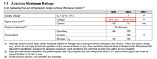
Best regards, Art
Hello Dear Art,
I am grateful for your answer. Yes, I am aware that these resistors will show a short circuit when viewed with a multimeter, and by saying there is no power in my circuit, I am sharing the results I see without applying voltage to any part of the circuit.
I would like you to look at the schematic in my previous answer. There is a short circuit between pins in my "15EDGVM-3.5-04P-14-00AH" connector. Pros and cons of LED.
Oben,
I assume you mean that you see a short between pins 2 and 3 of connector P8. Pin 3 has a connection to "Current monitor A". Current monitor A has a 0.1 ohm resistor to ground. This is basically a short. Between pins 2 and 3 there is also a transistor. Depending on how the transistor is biased it can also have a very low impedance. Also, the transistor has a diode across it which also can act as a short depending on the bias.
best regards, Art
Hello Dear Art,
Yes this is my problem, when I look at the this;
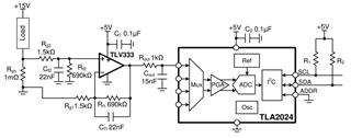
For my side everything is okay. Thats why when I removed the resistor there is no short circuit.
Am I put the voltage from P8's 1 or 2nd pins? Because my load is we can think P8.
Regards
Oben,
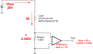
I am sorry, but I do not understand your question. In the image you show above your supply would be 15V to ground. The actual voltage delivered to the load would be across "load" in the schematic. This would be less than 15V as some small voltage would drop across the shunt resistor (1m ohm in this example).
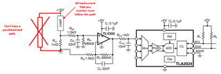
Maybe a key point for your design. You cannot have any load in parallel with the sense path. See image below.
best regards, Art