This thread has been locked.
If you have a related question, please click the "Ask a related question" button in the top right corner. The newly created question will be automatically linked to this question.
Tool/software:
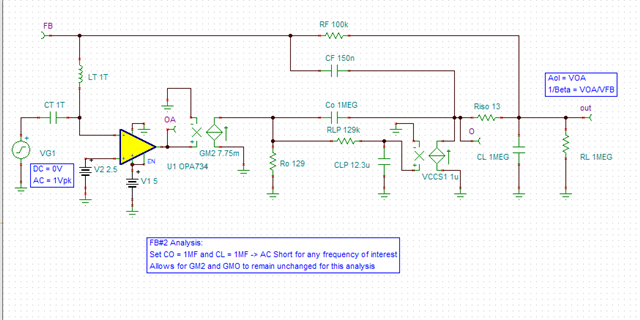
have been learning Tim Green's Stability for Op Amps serise articles for weeks. Now I have a problem when I simulate circuit in his part10 article.Circuit schametic as below,
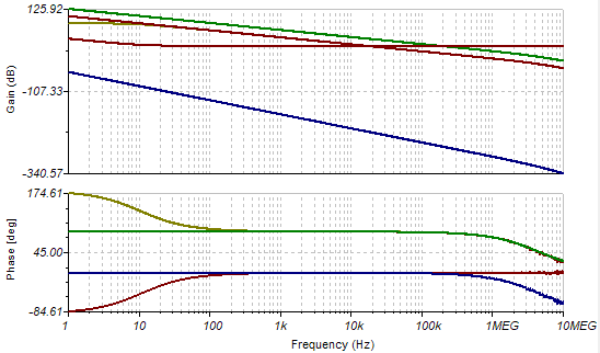
I input same circuit,and peform a AC analysis,results as below,
FB#2 Analysis AC Circuit CMOS RRO.TSC
What confuse me is that at high frequency,AC amplitude seems to be fluctuating rather than a smoth line.What's wrong with it?
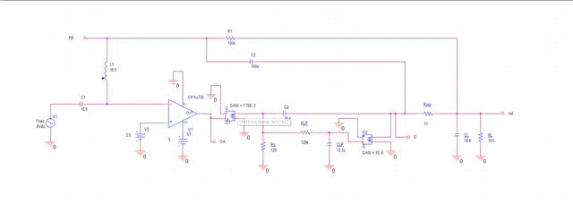
I also input a same circuit in Pspice and perform a bias analysis simulation,as below,
But it's annoying that simulation is stuck at "Starting pseudo-transient algorithm",I revise circuit a few times but I could find a proper circuit to make it work as long as two VCCS exists. I hope someone could offer some advise.
Question 1:Why there is amplitude fluctuation at high frequencies in Tina?
Question 2:Why same circuit as above couldn't peform a bias analysis in Pspice?
Hi Yang.
As you have mentioned, this is likely related to the TINA simulator unable to resolve the AC result over frequency while when using the large large capacitive at the input of the op-amp to inject the AC test voltage, and the large inductor used to break the loop. I was able to reproduce the issue, I will see if I can find a way to eliminate the issue on TINA. Please allow a couple of business days.
Thank you and Regards,
Luis
Hi Yang,
The response in that circuit goes down to -437 dB; the positive numbers go up to 125 dB. This is a huge range of numbers for the simulator to cover and would requires a resolution of ~10^-30. Basically the numbers at -437 dB are so small that they have reached the resolution limit of the simulator. Since that number is used in the calculations above it influences all of the waveforms. I would ignore this.
Regarding the inability of PSPICE to converge, it is likely also related to this very small number. You can likely decrease the size of the capacitor from 1G to 1M and it may help the convergence without impacting the curves in normal frequency ranges - please give that a try.
These examples are really just learning exercises; do you have a specific circuit that we can help analyze in your system?
Regards,
Mike
hello, Michael
Thank for your guidance about simulator, I revise capacitor Co and Cl to 1Meg farad,as below,CT and LT is revised also but turn out no influence.
Results doesn't appear abnormal influctuation as before,
But in Spice,I also revised same arguments,Co and CL even decreased to 1E4 farad. It doesn't work yet. Maybe Tina is better than Spice?
sorry as so for I am a learner, I want simulate some real circuit in order to understand it thoroughly,but for now I think I don't have adequate knowledge, I will analysis these circuit in future. Maybe I will bother you a lot of times then.
HI Yang,
Glad the issue on TINA-TI was resolved. PSPICE for TI can potentially be more sensitive to convergence on this particular open-loop analysis in certain circuits involving the large capacitors; although PSPICE offers other features. In general, I tend to perform the open-loop analysis in TINA-TI; but PSPICE-for-TI is also quite powerful offering Monte-Carlo on its free version and other features.
Thank you and Regards,
Luis
HI Luis,
Thank you for your opinion which make me konw more about TINA and Pspice. I do simulate in another simulator when one generate result differ from what I expect. I need to learn and think in deep to avoid to be a spice monkey.
Thank you and Regards,
Yang