This thread has been locked.
If you have a related question, please click the "Ask a related question" button in the top right corner. The newly created question will be automatically linked to this question.
Tool/software:
Hi,
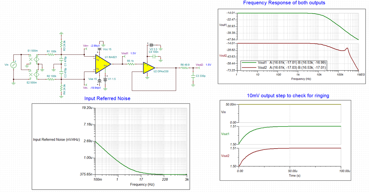
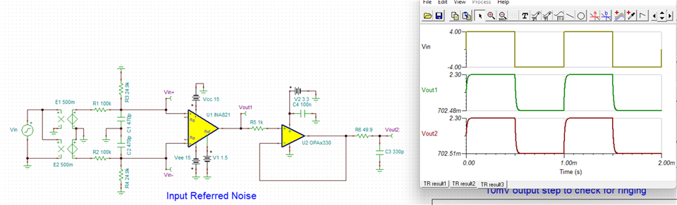
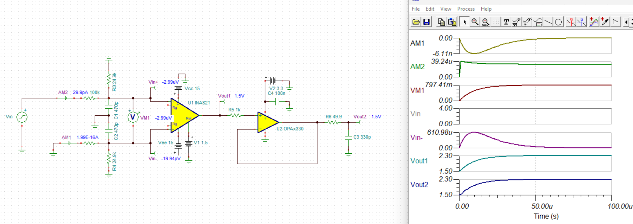
We would like our INA821 design to be reviewed:
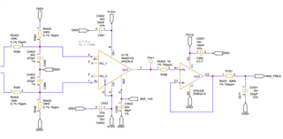
The input signal characteristics are the following:
This then feeds the CMPSS of a TMS320F28386D for frequency measurement using the CLB.
I also have a question, we are being asked if this would be compatible to acquire a single-ended 4V square wave, with negative input being connected to the GND.
From my understanding of the datasheet, I feel like this would be problematic as this would lead to unbalanced inputs as per requirement for Input Bias Current Return Path.
Best regards,
Clément
Hi Clement,
I will be reviewing this and will respond by the end of the day tomorrow.
Best Regards,
Chris Featherstone
Hi Clement,
I have put the circuit into Tina Ti to check it's general performance. I checked the frequency response, step response for stability and the input referred noise as well as the DC voltages. You can see the -3dB cutoff frequency occurs at 16.53kHz. Balancing on the input of the INA is crucial so we recommend high quality passive components to maintain the CMRR. I have attached my simulation to the bottom of this post. Tina Ti is a free download from this link if you would like to run the simulation.
https://www.ti.com/tool/TINA-TI
Best Regards,
Chris Featherstone
Hi Chris,
Unfortunately installing Tina Ti is complicated due to our IT rules.
Thank you for checking our design, we had low fear that it wouldn't work with a pure differential input.
However, you did not answer to the second part of my question.
I also have a question, we are being asked if this would be compatible to acquire a single-ended 4V square wave, with negative input being connected to the GND.
From my understanding of the datasheet, I feel like this would be problematic as this would lead to unbalanced inputs as per requirement for Input Bias Current Return Path.
I believe from your answer regarding the balancing and the fact that we would be trying to acquire with the INA a single ended analog signal, that this wouldn't work.
Clément
Hi Clement,
I ran the 4V square wave below. I am not sure what to look for to answer the question. The square wave is distorted due to RC time constants in the circuit but passes through fine.
Best Regards,
Chris Featherstone
Chris,
You didn't catch me.
In your simulation you still created a true differential signal.
What I was talking about is inputing a single-ended signal with the other signal of the front-end input connected to GND.
And as I stated I was seeking your advice but believed this won't work due to unbalance created on the input.
Clément
Hi Clement,
You are correct to say that an imbalance would be created on the input in this scenario. I ran the simulation shown below and am thinking through the results. Every pulse will create an imbalance in this fashion when applied single ended and the common mode signal will turn to differential and be see at the output. From a DC perspective I have the circuit biased as before so I think DC values are ok. The AC signal is creating the an imbalance however as you pointed out.
I am not sure what type of capacitors you are considering in the design in the signal path. I forgot to mention you may want to avoid X7R capacitors due to their high barium titanate content that create microphonics and act like little microphones.
I put a bill of material at the bottom of the post with some highlighted components we used for our OPA1637 fully differential amplifier evaluation module for some part recommendations. We recommend using COG/NPO type. Here are some resources:
https://www.edn.com/more-about-understanding-the-distortion-mechanism-of-high-k-mlccs/
I hope this information is helpful. Let me know if I can be of further assistance.
Best Regards,
Chris Featherstone
Hello Chris,
Thank you for your answer.
We intend to use C0G/NP0, so that's fine.
Clément