This thread has been locked.

If you have a related question, please click the "Ask a related question" button in the top right corner. The newly created question will be automatically linked to this question.

OPA627: Contemporary replacement for OPA111SM?

Part Number: OPA627
Other Parts Discussed in Thread: OPA134, OPA140, OPA145, LM124

Tool/software:

Hello,

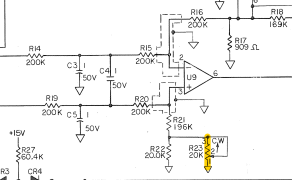
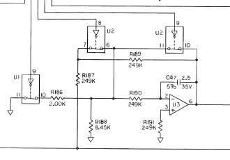
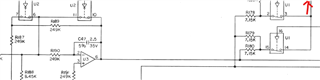
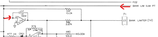
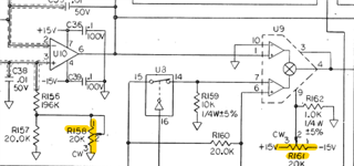
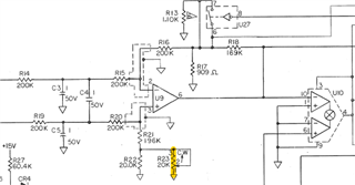
I work on legacy avionics systems made by J.E.T. These originally used Burr Brown 2A180 / Analog Devices AD3417 precision op amps, which were subsequently replaced by the OPA111SM. These are used as integrators/comparators in analog circuitry for Learjet autopilot computers.

Due to obsolescence of the above part, I am looking for a contemporary replacement. I see the OPA6x7 has been recommended in other circumstances for the same series and was wondering if the OPA627SM may be a good candidate.

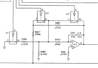
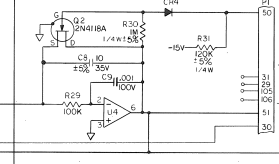
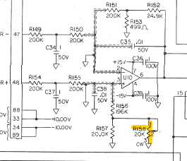
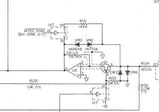
I have attached the source document specifying the necessary requirements for the part. The original package is TO-99-8; however we could fit a DIP-8 on the board with no modification.

577-1144.pdf

Thanks in advance for your help.

  • HI Shadyn,

    We have a few options of modern JFET input amplifiers offering better performance and precision than the legacy OPA111SM; however, these are not available on the PDIP or TO-CAN packages. The OPA627SM is a 45-MHz previous generation JFET amplifier that was formerly available on the TO-CAN (LMC) package, although this package option is no longer recommended for new designs.  However, the OPA627 remains active on the SOIC D (8) package version.

    The OPA134 is a FET input amplifier available on the PDIP package with GBW of 8-MHz; but is intended for audio performance applications so the DC offset and offset drift is higher than the OPA111.

    The opa145 (5.5 -MHz) and OPA140 (11-MHz) are newer generation JFET input amplifiers offering better offset precision, low noise, higher bandwidth.  Unfortunately, these are available on SOIC, VSSOP, and SOT23-5 packages and not on the PDIP nor the TO-CAN package.

    https://www.ti.com/amplifier-circuit/op-amps/precision/products.html#89=FET&480=1&1261max=15%3B36&

    Below is an excel file with the spec comparison of these amplifiers

    Compare-parametrics-2024112115378.xlsx

    However, there are other CMOS input options available on PDIP package. Let me know if you would like me to look into any single op-amps on the PDIP package.

    Thank you and Best Regards,

    Luis

  • Thank you for your reply.

    I should clarify that this is not for a new design; this is an attempt to find an available replacement for a component we can no longer source, in our efforts to provide continued support for legacy products. In other words, these would be used as replacements in repairs on existing systems, so it's imperative that we find something that not only performs in a similar manner to the original, but fits in the same footprint and uses the same termination (through hole). If push comes to shove I suppose we could use a SMD to DIP adapter.

    This is not an audio application; the output should be a clean DC signal with minimal drift.

    Seeing as there is available stock of the OPA627SM, we will be ordering a few to test in one of our bench units, but we are open to alternatives.

  • Hi Shadyn,

    Yes, the newer generation JFET precision amplifies are only available on the smaller packages unfortunately.

    You are correct, the OPAx627 is the only precision JFET input amplifier still available on the SMD package. The OPAx627 (45-MHz) may work fine on your application, however, keep in mind the OPAx627 device has significant higher BW than the OPA111 (2-MHz) you are attempting to replace therefore the frequency response and compensation/stability response may be different. If a detailed schematic showing the op-amp load, voltage supplies and application input signal and output signal characteristics/requirements is available, and if you believe is helpful, we could review the schematic and look at the circuit in detail.   

    There are other options with CMOS inputs on PDIP, and I believe there is the audio and some general purpose JFET amplifiers with higher offset on PDIP; but not the combination of precision, low offset, with JFET inputs on PDIP.

    Thank you and Best Regards,

    Luis

  • I can provide a few screenshots

    Most if not all of these are DC signals, and these are on two different boards: U3, U4, and U10 are on the A2 roll analog board and U8, U9 are on the A5 pitch analog board. Again, this is an autopilot controller computer so it controls two axis: roll and pitch of the aircraft

    A2U3 provides a "Course Error Washout" signal; its source is a 400hz course signal that is converted to DC by a LM124J

    A2U4 provides a "Roll Integrator" signal that is used to maintain the aircraft's roll attitude when the autopilot is engaged or synchronized; its source is a 400hz roll attitude gyro signal that is rectified and buffered by two stages of LM124Js

    A2U10 provides a "Lateral Beam Deviation" signal; its source is two DC signals that represent the localizer signals; its output represents the aircraft's position in regards to the runway centerline and is used to establish the aircraft on a precision approach course to the runway

    A5U8 performs a similar function to U4 but for the pitch axis ("Pitch Integrator); 400hz pitch attitude gyro signal is rectified and buffered through 4 stages of LM124J's and is used to maintain the aircraft's pitch attitude when the autopilot is engaged or synced

    A5U9 performs a similar function to U10 ("Glideslope Error") except it provides a signal that represents the aircraft's position in regards to the glideslope to the runway; its sources are DC signals from the glideslope receiver

    All signals that are converted from AC have a maximum RMS of around 250mV; in practice this is generally much lower.

    All 5 of these devices are provided +/- 15V DC ±750mV, as follows:

    Pin 4: -15v
    Pin 7: +15v
    Pin 8: GND

    I should probably mention that AD3417s were originally used in some earlier units, but the vast majority I've worked on have had 2A180s

  • Hello Shadyn,

    Thank you for the additional information. 

    The OPA627 has a slightly wider input voltage range than the OPA111, and slightly wider output voltage range, so I don't expect issues with the input output voltage range of the signals on the circuits above.

    I don't see any obvious issue, however, if you would like me to review/analyze each of those circuits in good detail for stability, I may need to ensure I understand a few more details.

    For example:

    - On partial schematic 1, kindly confirm, I am assuming these capacitor value units are on microfarads? i.e. is C47 2.5µF? 

    - What is the load at the amplifier U3 output (not shown)?

    - On partial schematic 2:

    - What is part P1? Is there any other load capacitance at the amplifier output?


    - Circuit 3 is a difference amplifier, provided that the circuit is working within its linear range, I don't see any obvious issues. Nevertheless, just as above, kindly confirm the capacitor values, and the load connected at the amplifier output. 

    The last partial circuit does not show the complete feedback connection or output load connections.

    Thank you and Kind Regards,

    Luis

  • Correct, all capacitor values are in µF.

    The output of A2U3 is broken out of the unit as a test point, I use digital multimeters and an oscilloscope to measure DC and RMS voltage at that point
    It is also switched into "Bank Limit Sum"

    Which is then routed into the input of another LM124, A2U13:

    So I'm not really sure what the load is.

    "P1" is the edge connector for the board; pins 50 and 51 are test points, but the output of A2U4 is "Roll Integrator Signal", which is also routed into the input of U13 through a 10k resistor.

    Capacitors are in microfarads as I mentioned above, so C34 and C37 are 1.0 µF, C36 and C39 are 0.1µF (100nF), C35 and C38 are 0.01µF (10nF)
    The output of A2U10 is monitored as a test point, and is routed into multiplier A2U9, an AD632SH/883B:

    Here is a better view of A5U10 which has a similar configuration to the above:

    Its output is also monitored as a test point and is routed into A5U10, another AD632SH/883B multiplier

    Sorry I can't provide complete schematics, these are proprietary materials so I have to be careful how much I show

  • Hi Shadyn,

    I performed a quick check for stability on the first circuit and third circuit; making the assumption the op-amps do not see a high capacitive or inductive load, which from the circuit description, appears to be a valid assumption.

    Performing the small-signal open-loop stability of this circuit, to simulate the Loop-Gain phase, yields to a phase margin of 80.5-degrees, which is quite stable (A conservative guideline for phase margin for stability is >45-degrees).  On this quick check, I assumed the switches U1 and U2 are closed.  Also, since the switches are in series with very large resistances, I neglected the parasitic capacitance of the switch on the stability. I also assumed that the load is not capacitive.  I think this circuit is quite stable.

    See simulation below. Added components C_Test, L_test is only for simulation purposes, to open the feedback on the SPICE simulator. Copa-parasitic is also for simulation purposes, to reflect the input capacitance of the op-amp.

    Circuit 1 simulation, switches closed.


    Similarly, I performed a quick check on the third circuit, U10, the difference amplifier with the T-feedback network.

    Performing the small-signal open-loop stability of this circuit, to simulate the Loop-Gain phase, yields to a phase margin of 75.5-degrees, which is also stable with plenty of phase margin. (A conservative guideline for phase margin for stability is >45-degrees).  

    See simulation below. Same as before, added components C_Test, L_test is only for simulation purposes, to open the feedback on the SPICE simulator. Copa-parasitic is also for simulation purposes, to reflect the input capacitance of the op-amp when opening the feedback loop...

    Thank you and Best Regards,

    Luis

  • I won't lie, that's all Greek to me but if your point is "it should work fine" then I appreciate it Slight smile

    We may experiment with the OPA145 as well using SOIC to DIP adapters

    Which of the products you've mentioned meet MIL-STD-883?

  • Shadyn,

    I'll jump in here as Luis and most of the staff are out for the US holiday.

    Our military rated devices have an M suffix.   I did a quick search of all op amps that are military rated and here is the result:

    https://www.ti.com/amplifier-circuit/op-amps/products.html#1498=Military&

    I looked at the list that Luis proposed earlier and I don't think any of those devices are military rated.  FYI.  We have a DIP-ADAPTER-EVM that you can use to convert to DIP format.  If I missed your point, Luis will return on Monday and can help with your question.

    Best regards, Art