- Ask a related questionWhat is a related question?A related question is a question created from another question. When the related question is created, it will be automatically linked to the original question.
This thread has been locked.
If you have a related question, please click the "Ask a related question" button in the top right corner. The newly created question will be automatically linked to this question.
Tool/software:
Hi,
I have been using the BUF634A to drive various resolvers. To improve the sinusoidal excitation, I tried implementing the resolver excitation circuit from your helpful application report. However, since I need steeper attenuation, I added a second filter stage, but I am getting much less gain than expected. Could you assist me in designing an excitation circuit that meets the following requirements?
Desired output is an 8kHz analog sinusoidal with a 22V peak to peak waveform. The input is a single ended 3.3V PWM signal. The temperature varies from -10 to 125°C.
Best regards
Victorio
Hey Victorio,
Could you share a schematic of the current design you have? Did you have satisfactory results with the existing setup in the application result?
Have you simulated your circuit in a SPICE simulator like TINA-TI or PSpice for TI? If so, could you share the project?
Best,
Jerry
The design using the BUF634A did not drive the resolvers differentially, resulting in a small difference between the upper and lower sine waves when a resolver is connected. To improve precision and achieve a higher output voltage swing, I would like to use the ALM2403 and drive the resolvers differentially.
Hey Victorio,
Thanks for sharing the schematic. This looks pretty close to what I would expect, I made a few changes to the design.
Ignore OP1, this is an ideal amp being used to buffer the 8kHz 0-3.3V PWM signal into the filter network.
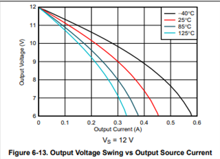
Is 22V Pk-Pk required? This may not always be possible at hot temperatures :

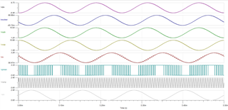
In my sim I have the output going to 19.5V Pk-Pk, but we could certainly bump the gain up a little bit If you are interested in a wider output swing.

Here is the simulation file:
Please let me know what you think of this circuit. Once we finalize the circuit design, we can go into the power calculations for this device.
125C operation can be tough with a power amplifier since we need to be concerned with power dissipation causing our die temp to increase to dangerous levels.
The recommended operating conditions in the datasheet state a max temperature for this device to be 125C, and the abs max die temp to be 150C.

Best,
Jacob