A related question is a question created from another question. When the related question is created, it will be automatically linked to the original question.
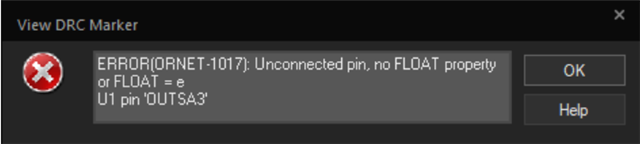
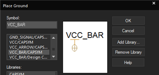
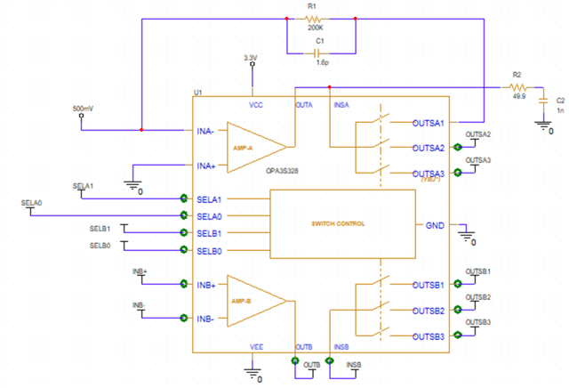
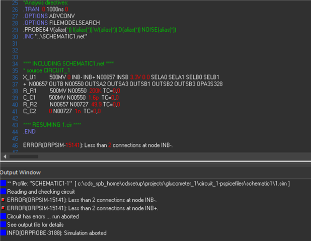
This can be fixed by providing connections to the pins that are highlighted in green. You can place a net label pin by pressing G, then scrolling down to the VCC_BAR/CAPSYM. This can then be placed on the pins and given an arbitrary (but unique for each pin) name, and it should be able to work. However, for the GND pin, I would connect that to GND.
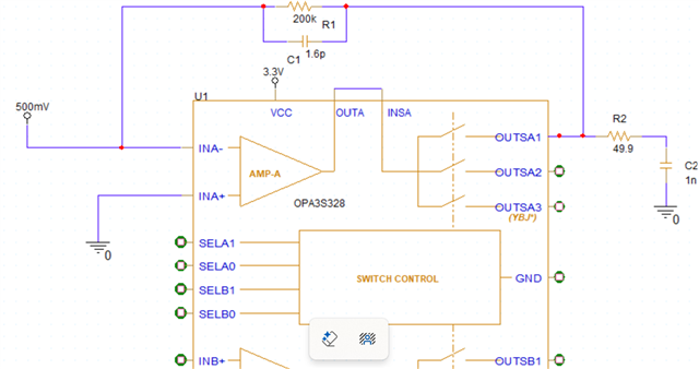
It seems you are required to configure amp-B. I would connect INB- to OUT and INB+ to some voltage between VCC and VEE. Additionally, it seems you are grounding IN+ of amp-A, and forcing 500mV on IN-. This will cause the output to rail low. Is that your intended function?
We wanted to use only single Opamp (AMP-A). Other Opamp (AMP-B) is not required in our application. What needs to be done for the NC (Not Connected) pins of (AMP-B).
And will recheck the circuit for inverting amp/ non-inverting amp function.
Please see the above application note for how to configure the unused amplifier. Even if just one amplifier is needed, you must configure the other amplifier in a linear range, or there may be excess current consumption or at worst, damage to the device.
Please make sure that a valid input and output common mode range is considered. If the input is connected to GND (easiest, but will not have valid output common-mode range), it is recommended that you add at least a 1k series resistor from the input to GND, to limit current in the case of a GND bounce.