OPA838: Transimpedance amplifier ringing and issues

Part Number: OPA838

Tool/software:

Hi,

I am implementing a transimpedance amplifier based on the OPA838 and I am experiencing oscillation. The following circuit (figure 1) has been implemented based on the sensor specification and the Application and Implementation (section 9) of the datasheet. Figures 2a and 2b show the transient response and frequency response of the circuit, respectively. I applied a sine current input (Id) having an amplitude of 1mA and 1 MHz.

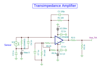
Figure 1. TIA circuit.

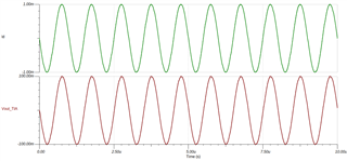
Figure 2a. TIA input and output signals. Id (green) sensor current signal; Vout_TIA (red) output voltage of TIA.

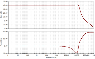
Figure 2b. Frequency response of the circuit.

So while I was implementing this circuit in the lab, I noticed an oscillation in the TIA's output. The waveforms are shown below:

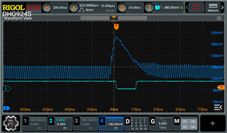
Figure 3a. TIA output voltage (blue); a trigger signal (cyan)

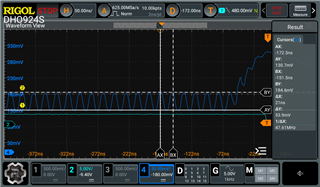
Figure 3b. Zoom in on oscillation

• How do I suppress this oscillation and what could be its source?

• What are the gain restrictions for the transimpedance topology using this operational amplifier?

Thanks.

  • Hi Adelson,

    I tried to design your circuit using the TIA Calculator Tool that we have recently developed, as per the tool the Cf suggestion for a q-factor of 0.7 is ~105pF. This value is calculated by considering opamp's inverting input cap and photodiode junction cap also. So I would suggest try using a Cf of 105 to 110pF in your circuit to achieve better stability. 

    How do I suppress this oscillation and what could be its source?
    You can suppress the oscillations (or increase TIA stability) by increasing the Cf/ feedback cap of the TIA. You can do the same by increasing Rf, but that would change the gain of TIA. Increasing Cf and/ or Rf will also reduce the TIA bandwidth.

    What are the gain restrictions for the transimpedance topology using this operational amplifier?
    The gain restrictions of TIA are set by your requirements of output voltage, TIA bandwidth and circuit stability. If you use a very large Rf or set a large TIA gain, then this would possibly make your circuit unstable because there will be a pole in the feedback loop of TIA caused by Rf, inverting input cap of OpAmp and photodiode juction capacitance.

    Also please try the tool and let me know what do you think. The tool also suggests devices suitable for your requirements, and there is also comprehensive noise analysis in the tool.

    Tool link: Analog circuit design studio

    Regards,
    Aditya

  • Hi,

    We would love to hear your feedback on the tool mentioned above: its usability, accuracy and any improvements you'd suggest. Please let us know your thoughts!

    Regards, Aditya