This thread has been locked.

If you have a related question, please click the "Ask a related question" button in the top right corner. The newly created question will be automatically linked to this question.

INA4180: Current sense amplifier minimum sensitivity

Part Number: INA4180
Other Parts Discussed in Thread: AM3358

Tool/software:

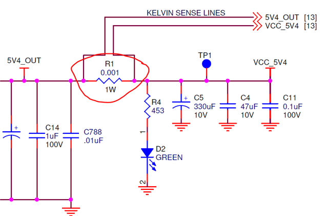
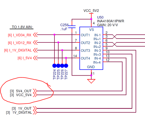
We are using the INA4180A1IPWR sense amplifier with a 0.001 ohm current sense resistor.  We're attempting to measure between 6 and 7 amps of current through the .001 ohm resistor.  That produces between 6 mV and 7 mV at the input of the sense amplifier.  Is this level of voltage too low for accurate current measurement?  Are there noise issues?  We are seeing about 180 to 190 mV at the output which is indicating too high (should be seeing 120 mV to 140 mV).  

  • This device has input offset error of up to 150 µV.

    What are the tolerances of the resistor? Can you show the schematic and the board?

    In general, you should size the resistor for the largest voltage drop that you can afford.

  • Clemens,

    Thanks for the quick reply.  The resistor is a 1%, 1 watt, Bourns CRK0612-FZ-R001E (R1 in the left schematic below), which is connected via sensing traces to pins 12 and 13 of the INA4180, U50 (next schematic below).  The layout of the sensing traces can be seen at the far right image, which is a snip of the R1 resistor area from our layout artwork.  The 150 μV maximum offset, x20, would add a worst case error voltage of 3 mV.  We're seeing a much larger error than 3 mV.  Would there be any other reasons that a larger error value would appear at the output?  We could increase the sense resistor value, but our output voltage accuracy level (5.40 V) would start to degrade as a function of load current.  


  • Hey Mike,

    I apologize for the weekend delay.

    I am look over this thread and will respond shortly.

    Best,

    Peter

  • Hey Mike,

    There is one potential non-idealistic aspect of shunt layout: there is curvature in the expected current density across the shunt. So most current will want to take shortest path around this curve which could result in significant gain (shunt resistance) error.

     I would confirm this by using a precision multimeter to measure the INA4180 input pins (right at the IN+ and IN- pins). 

    Another layout cause could be solder resistance of the shunt resistor in the force path of current ( so no proper Kelvin sense connections across shunt.

    Othee causes could be inaccurate measurements of current or even error associated with ADC. If measuring INA4180 always measure with respect to device GND pin.

    Lastly you should confirm there is no ground loop between INA ground and the load return. I see that there are two different ground symbols. I would use a differential multimeter or probe to measure to the voltage difference between these two grounds to confirm this.

    Sincerely,

    Peter

  • Hi Peter,

    These are good considerations to check out.  We will take measurements where we can to understand the actual voltage drop across the sense resistor, and also ground offsets.  In the design we are using an OSD3358 SiP (Octavo) containing the AM3358 processor with on-board 12-bit A/D to measure the output of the INA4180.  The AGND_ADC goes through a small ferrite bead inside the SiP to the processor GND.  We also have an AGND that the INA4180 is connected to.  The system AGND is connected to our main GND (same as processor GND) through multiple ferrite beads in the board layout.  We will look at the various GND offsets with an accurate meter, along with the sense resistor voltage drop, and let you know what we find.  Appreciate these suggestions.

    Regards,

    Mike