TLV171: Ref Design: TIDA-01352

Part Number: TLV171

Tool/software:

Hello,

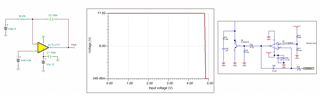
In Figure 14 on page 17 of the Design Guide: 400-W Continuous, Scalable, +/-2.5-to +/-150-V, Programmable Ultrasound Power Supply Reference Design (TIDUCD8.pdf), there is a table for VOUT-P1 (V) and VCON-A1 (V); it shows that for VOUT-P1 = 150V, VCON-A1 is 5V.  

Should VCON-A1 be 4.83871 V (=150*10k/310k) when VOUT-P1 = 150V?  Thanks.

Best regards,

Mark Liang

  • Hi Mark, 

    Should VCON-A1 be 4.83871 V (=150*10k/310k) when VOUT-P1 = 150V?

    Yes, your calculation is correct. The voltage divider at pin3 of TLV171UDBVR is (10/310)*150 = 4.83871V, and the U2 circuit is an integrator

    But VCON-A1 is controlled by DAC, which is defined 5V by DAC. 

    If you have additional questions, please let me know. 

    Best,

    Raymond

  • Hi Raymond,

    Thank you for your reply. 

    What are the reason for VCON-A1= 3.22581V and 1.6129V, when VOUT-P1=100V and 50V respectively in Figure 14?

    Best,

    Mark

  • Hi Mark, 

    These are the voltage divider calculation based on the figure 14. 

    If you have other questions, please let us know. 

    Best,

    Rayond