This thread has been locked.

If you have a related question, please click the "Ask a related question" button in the top right corner. The newly created question will be automatically linked to this question.

TLV171: The voltage follower circuit design with TLV171

Part Number: TLV171
Other Parts Discussed in Thread: TINA-TI, OPA171

Hi team,

My customer is using TLV171 to design a voltage follower circuit. When I tried to simulate with TINA-TI, I find that the Vout=10.2V with Vin=12V. Why the Vout is not equal with Vin? Could you please help to explain the reason or recommend a suitable device to design a follower? Thanks!

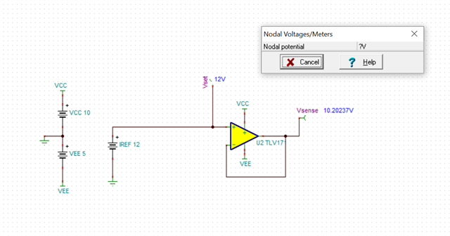
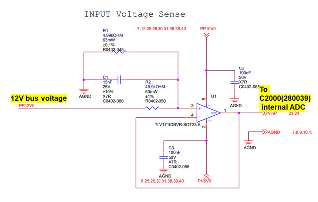
Actually, the circuit in their design is not 1:1 proportion. Could you  please help to modify?

BRs,

Rannie

  • Hello Rannie,

    This simulation result is not accurate, but it is intentional. OPA171 is not a true rail to rail input op amp. The actual performance at the upper end of VCM is not very good.   

     In the bottom schematic, I don't see an obvious issue. Can you provide the data for it?