Tool/software:
Hello,
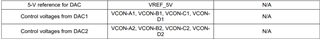
In Figure 14 on page 17 of the Design Guide: 400-W Continuous, Scalable, +/-2.5-to +/-150-V, Programmable Ultrasound Power Supply Reference Design (TIDUCD8.pdf), there is a table for VOUT-P1 (V) and VCON-A1 (V); it shows that for VOUT-P1 = 150V, VCON-A1 is 5V.
Should VCON-A1 be 4.83871 V (=150*10k/310k) when VOUT-P1 = 150V? Thanks.
Best regards,
Mark Liang
Hi Mark,
Should VCON-A1 be 4.83871 V (=150*10k/310k) when VOUT-P1 = 150V?
Yes, your calculation is correct. The voltage divider at pin3 of TLV171UDBVR is (10/310)*150 = 4.83871V, and the U2 circuit is an integrator
But VCON-A1 is controlled by DAC, which is defined 5V by DAC.
If you have additional questions, please let me know.
Best,
Raymond
Hi Raymond,
Thank you for your reply.
What are the reason for VCON-A1= 3.22581V and 1.6129V, when VOUT-P1=100V and 50V respectively in Figure 14?
Best,
Mark
Hi Mark,
These are the voltage divider calculation based on the figure 14.
If you have other questions, please let us know.
Best,
Rayond
Hi Rayond,
Thank you for your reply. This is going back to my original question: Should VCON-A1 be 4.83871 V (=150*10k/310k) when VOUT-P1 = 150V?
And your calculate also showed that as well, as you showed it on the dark blue. Therefore the 5V on that table of Figure 14 is incorrect, right?
Best,
Mark
Hi Mark,
Therefore the 5V on that table of Figure 14 is incorrect, right?
I have shown you how to calculate the voltage. This is a comparator circuit and and VCON-A1 is controlled by DAC. If the design is intend to turn off Q4, then 5Vdc is correct. You have to look at the context of the circuit.
Best,
Raymond
Hi Raymond,
What was the design intend in this reference design for the feedback circuit, for VOU-P1 = 50V, 100V, act as feedback, but for 150V turned off Q4?
Best,
Mark
Hi Mark,
Please read the application note and design requirements. I do not know what is the design intend, since our team did not put out the app. note.
Here is how the circuit works. Please see the simulation
TLV171 comparator 03242025.TSC
If you have other questions, please let us know.
Raymond
Hi Raymond,
I asked the question after studying the app note.
Could you please either put me in touch with the people who wrote the app note, or pass my question to the team? Thanks.
Best,
Mark
Hi Mark,
It looks like TIDA-01352 is supported by the Medical team. I will transfer you to the support.
Keep in mind that the mentioned circuit is a comparator, and I have sent you the simulation file and you should play round the comparators input and figure out when the output is activated or deactivated.
Best,
Raymond
Hi, Mark
nice to e-meet you in here.
1. for your initial issue. yes. you are correct.
2. in ultrasound imaging application, the transmitter generally is a 5 level or 3-level transmitter. let us see a typical 5-level transmitter from TI. the part number is TX75E16. it is a 5-level transmitter and maximum power supply is 100V. then the 5-level is -100V, -50V, 0V, 50V, 100V in general. this is the reason why designer show 50V in application note. for details, refer TX75E16 datasheet.
3. the U2 & U5A in here is error-amplifier. since the DC gain of error-amplifier is unlimited big, then the samples of output voltage will equal external control voltage.
hope it is helpful. thanks.
regards,
Bill