Part Number: PGA309EVM-USB
Other Parts Discussed in Thread: PGA309
Tool/software:
Hi team,
we want to calibrate the offset of a bridge with the PGA309 and we have some questions here.
For testing we use the PGA309EVM and the PGA309 GUI. To test the calibration we switched from the EEPROM configuration to the test mode. I already went through a couple of e2e posts but could not find a solution so far. If I have overseen them please let me know.
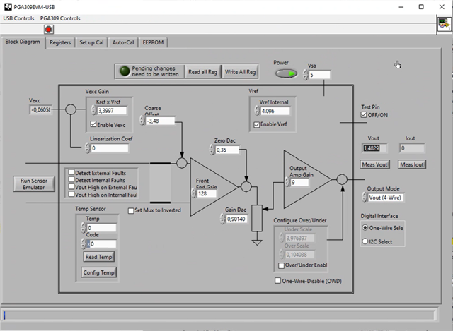
1. We observe that if we change a value in the tab 'Block Diagram' of the GUI the value is overwritten after a 'Read all Reg' was performed. Please note that we already changed into the test mode. Why does it overwrite the value?
2. Alternatively we think about changing the EEPROM configuration. For clarification: In the GUI a 'Load EEPROM With File' option is given. This does not write data in the EEPROM instead this writes the EEPROM data into the device's registers? I found the e2e post PGA309EVM-USB: Load EEPROM with file. To program the EEPROM they would need to follow the steps mentioned in PAG309 problem with EEPROM?
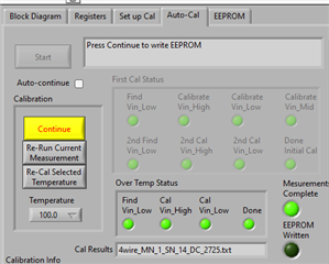
3. Can you please help me to understand what is the difference between the manual and automatic calibration? Are there limitations of the automatic calibration?
Can you please help us with our questions?
Best regards
Felix