TIPD184: Question about 450A detection

Part Number: TIPD184

Dear TI experts,

My customer tests their own PCB based on TIPD184 reference below ;

www.ti.com/.../TIPD184

  1. Is Primary current(A) vs Output voltage(V) determined by R6 and R7? or just only determined by R7?

image.png

image.png

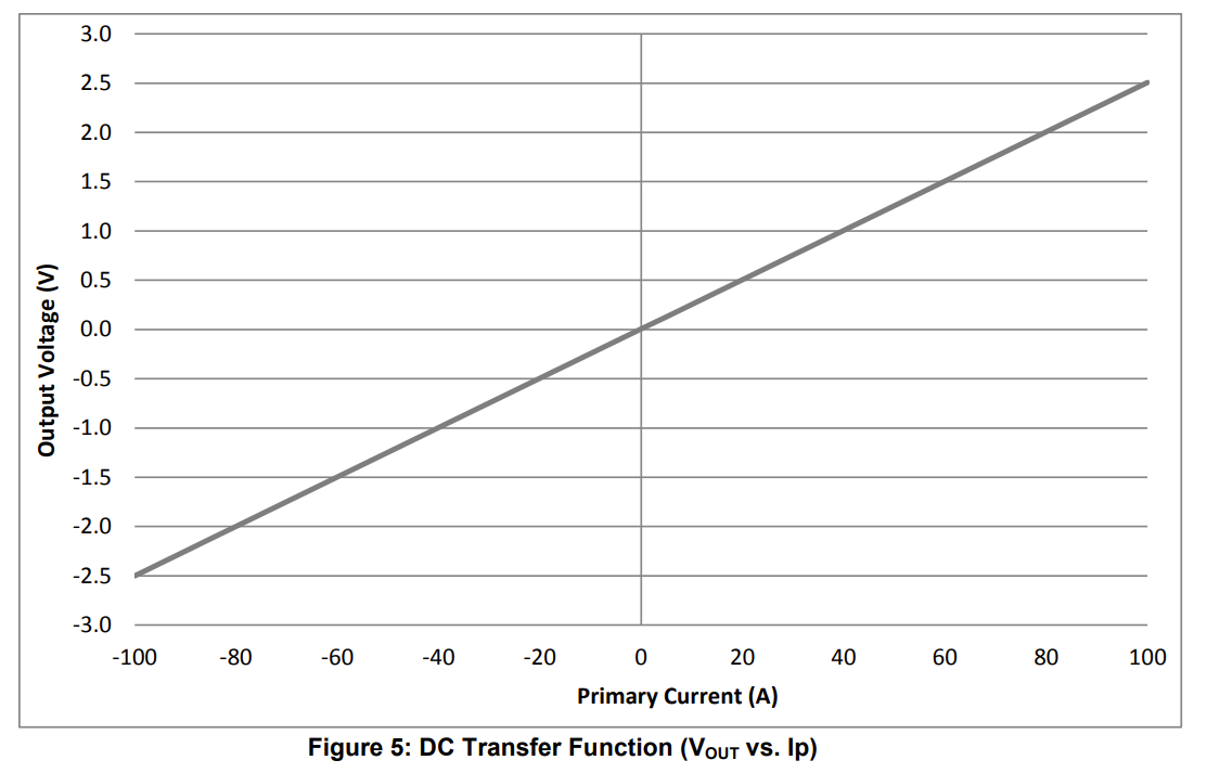
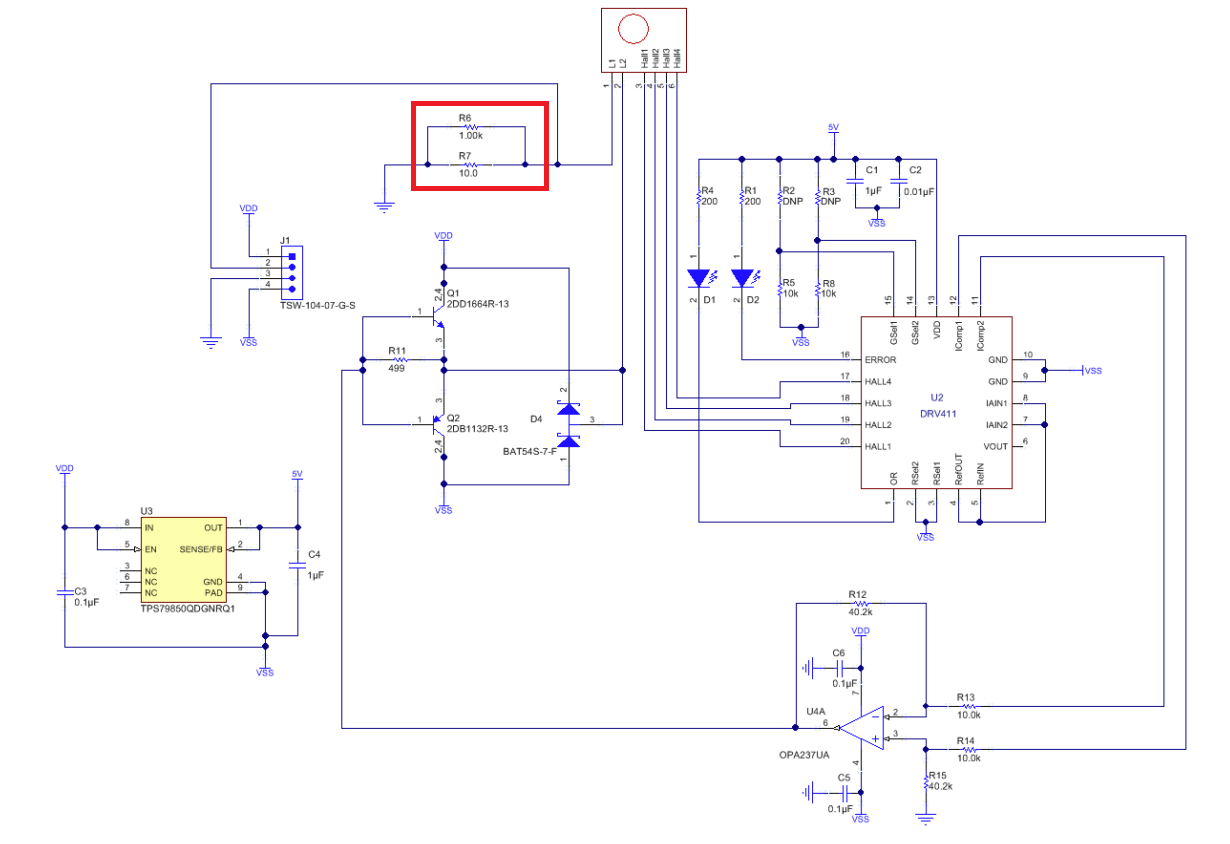
2. If my customer wants to detect 450A curremt, Could you guide how can I change the value of R6 and R7? - R6:1kohm, R7:11.11ohm?

(My customer will use 2000-turns coil for detection.)

3. I cannot see R6 in Bill of materials in TIDU820 document. Is it necessary?

www.ti.com/.../tidu820.pdf

Please check these issues. Thanks.

Best regards,

Chase

  • Hello Chase, 

    Thank you for your post. 

    1. The DC transfer function is determined by Rshunt. In this case, it is the parallel combination of the two resistors.
    2. Please see this post for all considerations: (+) DRV411: design consideration for drv 411 - Sensors forum - Sensors - TI E2E support forums
    3. No, it is not necessary. It changes the total shunt resistance to 9.9Ω. Rshunt should be sized according to your customers design requirements. 

    Best Regards, 

    Joe

  • Dear Joe,

    Thank you for your support.

    I have additional questions.

    1. About your answer #3, you said that R6(1kohm) is not necessary. But If we remove R6 and measure the current I cannot see anything from the output.

    Is it true that R6 is not necessary? Or does it have a range? (because it is shunt combination of R6 and R7, it is equally 10||10K=9.9ohm)

    2. In TIDU820 document, R7 is 49.9ohm in BOM, 10ohm in the schematic. Which one is right?

    Best regards,

    Chase

  • Hello Chase, 

    Thank you for the follow-up. 

    1. About your answer #3, you said that R6(1kohm) is not necessary. But If we remove R6 and measure the current I cannot see anything from the output.

    Is it true that R6 is not necessary? Or does it have a range? (because it is shunt combination of R6 and R7, it is equally 10||10K=9.9ohm)

    Can you perform a continuity check across R7 to confirm that it is 10Ω when R7 is removed? 

    2. In TIDU820 document, R7 is 49.9ohm in BOM, 10ohm in the schematic. Which one is right?

    As discussed in this E2E post, the correct shunt resistor is 49.9Ω.

    (+) Current sensors and the bi-polar swing - Precision Hub - Archives - TI E2E support forums

    Best Regards, 

    Joe

  • Dear Joe,

    Thank you for your support.

    My customer is very confused about shunt resistor.

    1. Regarding to the schematic, it is combination of R6 and R7. And you said that correct shunt resistor is 49.9ohm.

    Is 49.9ohm the combination of R6 and R7? Or just the value of R7? (in this case the final shunt resistor value is 49.9 || 1K = 47.53 ohm)

    2. Please check that my customer can use 50ohm(49.9ohm) shunt resistor if maximum current value is 450A.

    3. How about the tolerance of resistor? F(+/-1%) is okay? Or should I use more precise resistor?

    I am asking it because my customer said that the result is very different regarding to just 0.x ohm of difference.

    Please check these issues. Thanks.

    Best regards,

    Chase

  • Hello Chase, 

    The shunt resistor for the reference design is incorrectly documented as 10Ω in the reference design in parallel with a 1kΩ. 

    As the post I shared with you stated, for the current requirement from that reference design, should be 50Ω for ±100A. For your customers design with 450A, the right shunt resistor is 11Ω. 

    The tolerance of their resistor depends on their error requirements. If they want to reduce the error then I would recommend a 0.1% resistor. 

    I hope this helps, 

    Joe

  • Dear Joe,

    Thank you for your support.

    Let me clear just 1 thing again ;

    - For my customer, the value of shunt resistor should be 11.11111.... ohm, it is the combination of R6 and R7, or 11ohm of one resistor is also okay.

    Am I right?

    Best regards,

    Chase

  • Hello Chase, 

    Yes, you are correct only one resistor is required and I would recommend that they first try 11Ω as it is a standard resistor value.

    Best Regards, 

    Joe

  • Dear Joe,

    Thank you for your support.

    Is there any reason that use 2 combination of parallel resistors instead of one resistor in the reference?

    I think one resistor is more simple and easy to use.

    Best regards,

    Chase

  • Hello Chase, 

    There is no reason for this in the reference design. 

    I can see a use case where the resistor value is not standard and a parallel combination makes the ideal value easier to achieve. 

    I hope this helps, 

    Joe