


Part Number: OPAMP-NOISECALC
Other Parts Discussed in Thread: OPA892
I am designing a current source whose output will be switched at a frequency of 600 kHz. I have used an OPA892 to close the feedback loop, as shown below.
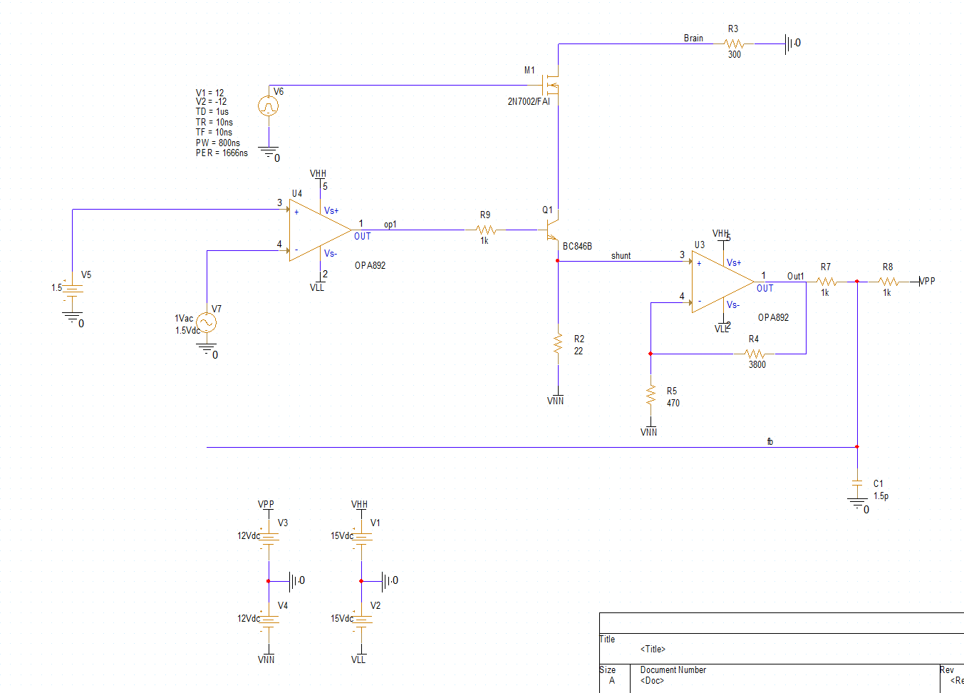
Since I observed instability, I opened the feedback loop to analyse the open-loop frequency response. I then plotted V(op1) in dB, which I expected to simply represent the open-loop gain of the first op amp. 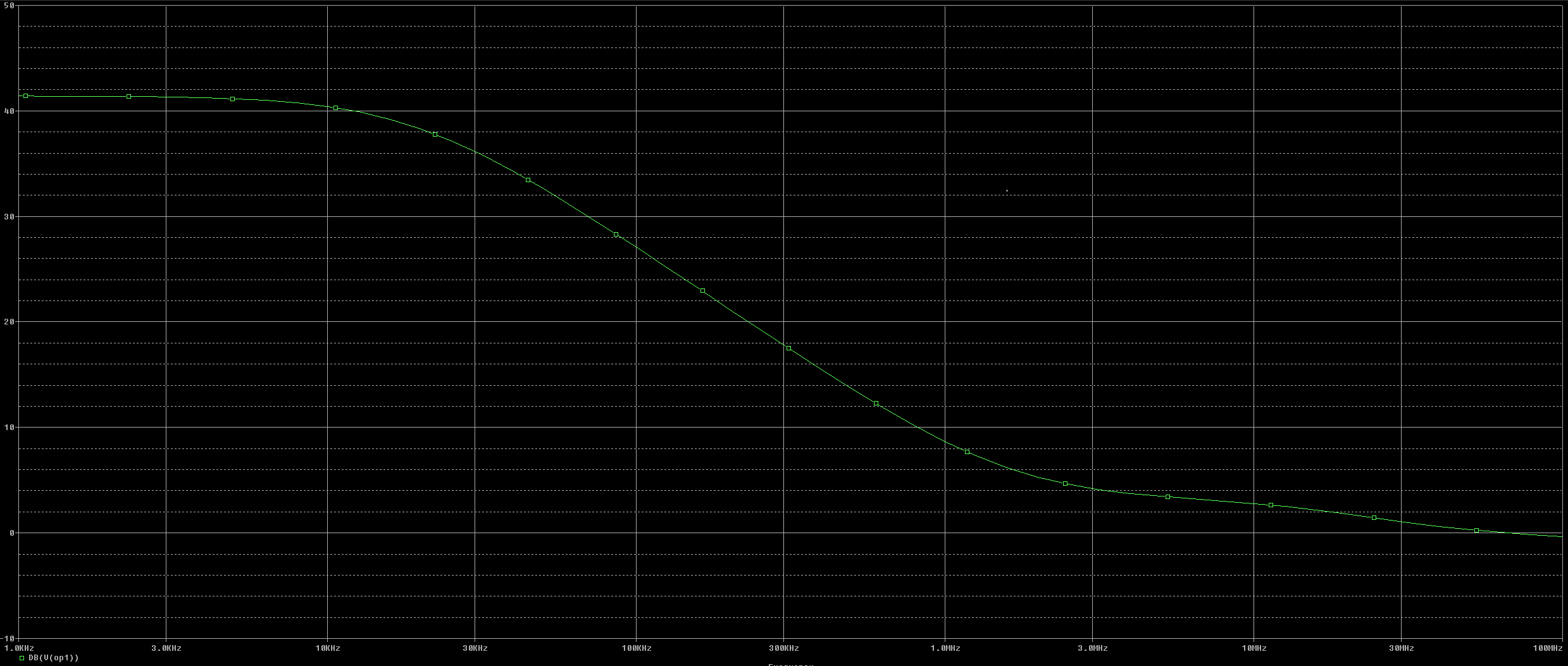
However, the simulated DC gain is only around 40 dB, and the unity-gain bandwidth is around 66 MHz. This differs significantly from the datasheet graph, which shows a DC gain of approximately 100 dB and a unity-gain bandwidth of around 1 GHz. 
Where does this discrepancy come from, and how can I trust the simulation results?
