LMH6611: LMH6611 Schematci and application check

Part Number: LMH6611
Other Parts Discussed in Thread: TINA-TI, OPA891, OPA810, OPA2891

Tool/software:

Hi TI expert team,

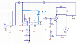
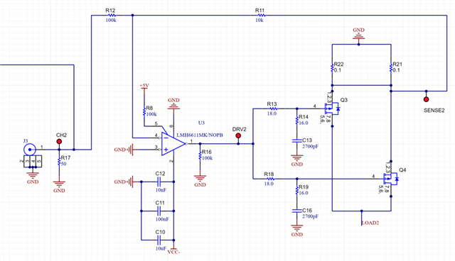
     I 'm using the LMH6611 to develop a small circuit to drive a negative power load as below fig. Coudl you help me to check whether it is achieveable or any mistake?

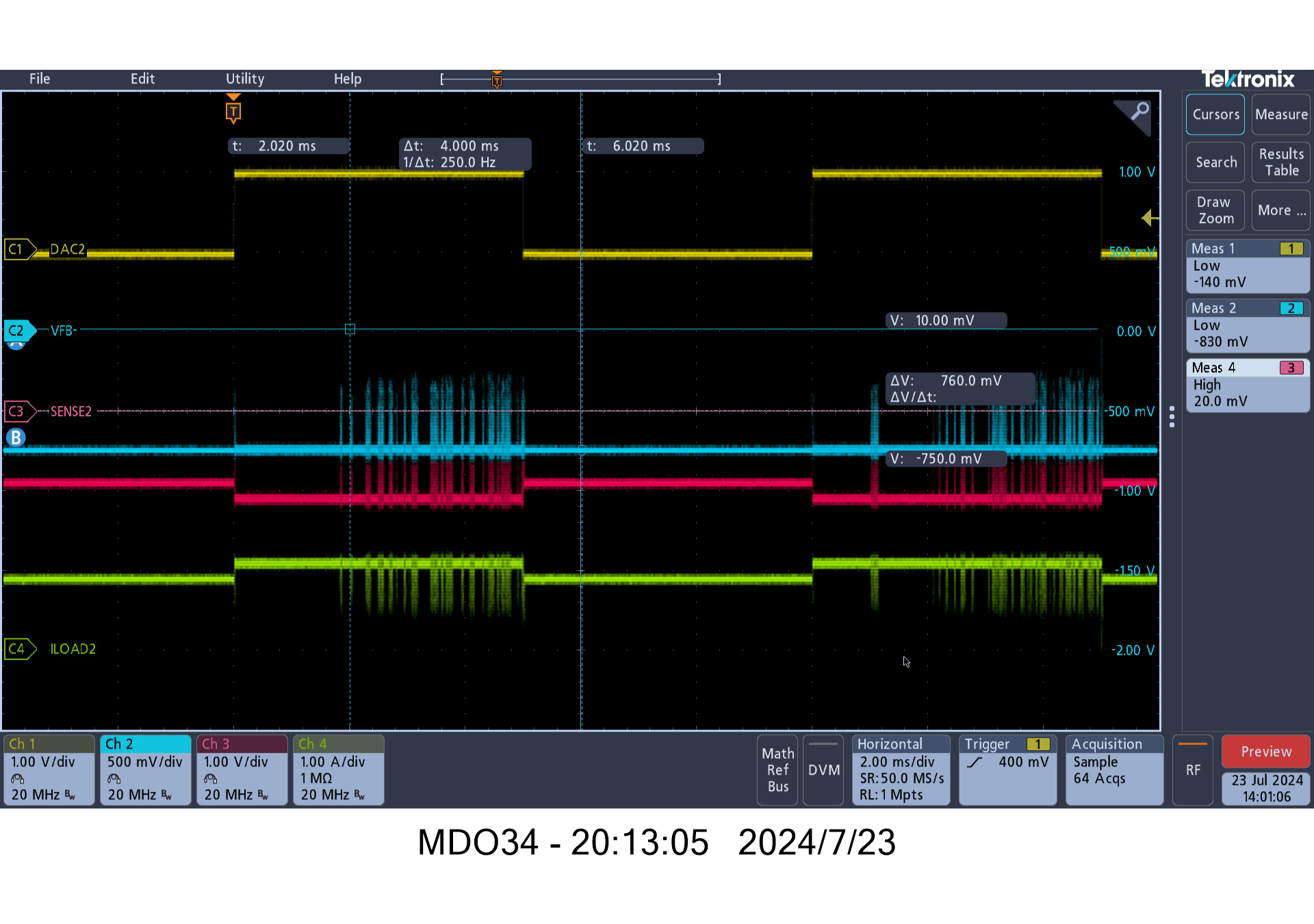
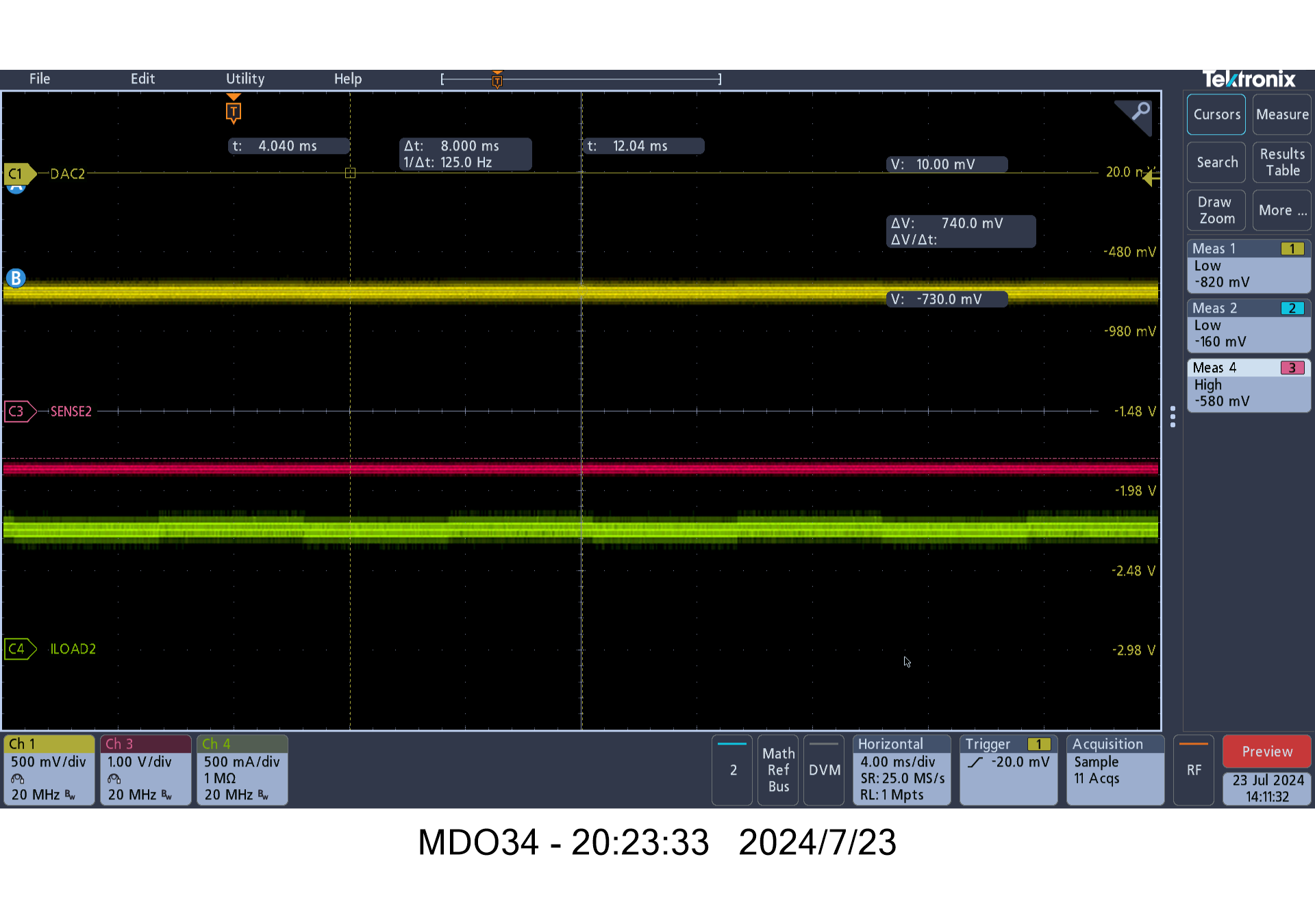
     Where CH2 vin soure from 0V to 5V, Iout could be controled from 0A to -10A. 


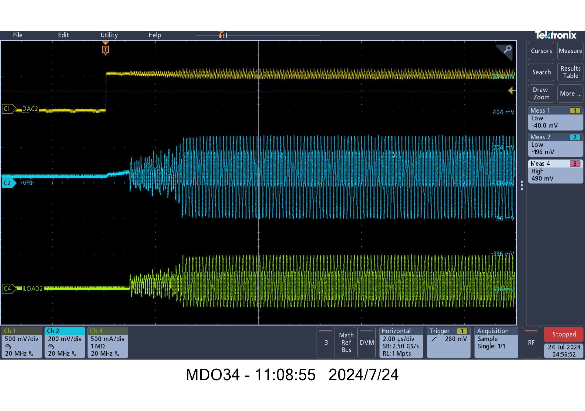
     And is there any spice mode for the LMH6611 that I can import to LTspice or Simetrix to simulate this solution?  I want to evaluate the loop stability of this circuit. Thanks a lot.

     And since LMH6611 is a old device, is there any a new device with similar feature with the LMH6611?

BR

Sean


  • Hello Sean,

    I may have some newer device suggestions for you once I look over your circuit application.

    In general, you can take TINA-TI and PSPICE models and use them in other simulators if you can accept any limitations.  There are previous threads about using a PSPICE model (the one for LMH6511) in other simulators.

    Best,

    Alec

  • Hi Alec,

        Any more suggestion? Thanks

    BR

    Sean

  • Hello Sean,

    I will need some more time this week to look at your circuit.

    Please expect an update by the end of the week.

    Thank you.

    Best,

    Alec

  • Hi Alec,

        I have build a test board with above sch, where I changed the R21=R22=1ohm for low current test, when I input the DAC2 with 1V, 50% square signal, I hop to get the load current as 200mA 50% square wavefrom. But here is the test waveform, I don't know what's wrong with that circuit. Could you help me?

    test results

    When the DAC2 amplitude is 0mV, It hopes that VFB-=0mV, but here I get about -750mV, do you what's the reason. It is urgent for my project, Hope for answer as soon as possible. Thanks.

  • And I have tried to replace R11=R12=0ohm, here is the test results, it seems the VFB-=-730mV whetehr is there input signal or not.

    DAC2 pin is connected to a signal generator which output impedence is 50ohm.

  • Hello Sean,

    I agree these waveforms are not ideal and that your circuit needs debugging. 

    Does your circuit improve if you try putting a DC bias voltage on the non-inverting pin of the LMH6611?  This would be pin 3 on the PCB.  Your circuit may need a resistor between the non-inverting input and GND, allowing for some DC voltage offset and for the inverting input node to be at a non-zero voltage.

    I will take a look in simulation as well.

    Best,

    Alec

  • Hi Alec,

        I have tried to solder a 10k resistor between pin 3 to GND, but it behavious as above. Is there any other reason? I don't understand why the pin 4 has a large negative voltage even input signal is zero. Thanks.

    BR

    Sean

  • Hi Alec,

        I also have tried with connect a +5V power rail to PIN6, it seesm better, but It still not regulate as expected as below:

        Even VIN=0, VFB-(PIN4) still not zero, and There seesm not stable as below:


        Is there any suggestion for debug? Thanks.

    BR

    Sean

  • Hello Sean,

    This seems to be a possible stability issue.

    Another fix to try is adding a local feedback loop using a capacitor from the amplifier's output to the inverting input.  This is an open circuit at DC but for AC signals looks like a short as the frequency increases.

    Please try adding in a capacitor between inverting input and the amplifier output to stabilize the circuit.

    Best,

    Alec

  • Hi Alec,

        Actually I have a cap between the inverting pin and output, but it seems doen't improve it from the root cause. Here is my debug result with different caps, Could you help it? Thanks.

       debug list.pdf

    BR

    Sean

  • Hello Sean,

    Thank you for sharing your debug list.  May I recommend a capacitor as drawn in the following diagram?

    Diagram: 

    Thank you.

    Best,

    Alec

  • Hi Alec,

         it is much better to add a cap directly between PIN4 and PIN1. But there is a new problem, it seems for this application ,it must use the unipoloar power supply instead of single power supply. 

         I have tried with the single power rail, there is a DC bias voltage.

         And is there similiar new device with wider power supply range for +/-10V with high output current capability, high slew rate, and high speed and low cost.

        I have find the OPA810 and OPA891, how about this two?

    BR

    Sean

  • Hello Sean,

    I do recommend working with the OPA891 and OPA810.  The OPA891 is a part of our family of high-voltage, low noise op-amps.

    We also have the OPA2891 if you require a dual-channel amplifier.  Thank you for trying and testing the method I recommended.  

    Best,

    Alec