This thread has been locked.

If you have a related question, please click the "Ask a related question" button in the top right corner. The newly created question will be automatically linked to this question.

min GBW requirements by FILTERPRO design

Other Parts Discussed in Thread: OPA1662, OPA835, OPA376, LMP7731, OPA2320, OPA320, THS4521

Dear Sirs!

I'm trying to design bandpass filter, using FilterPro soft.

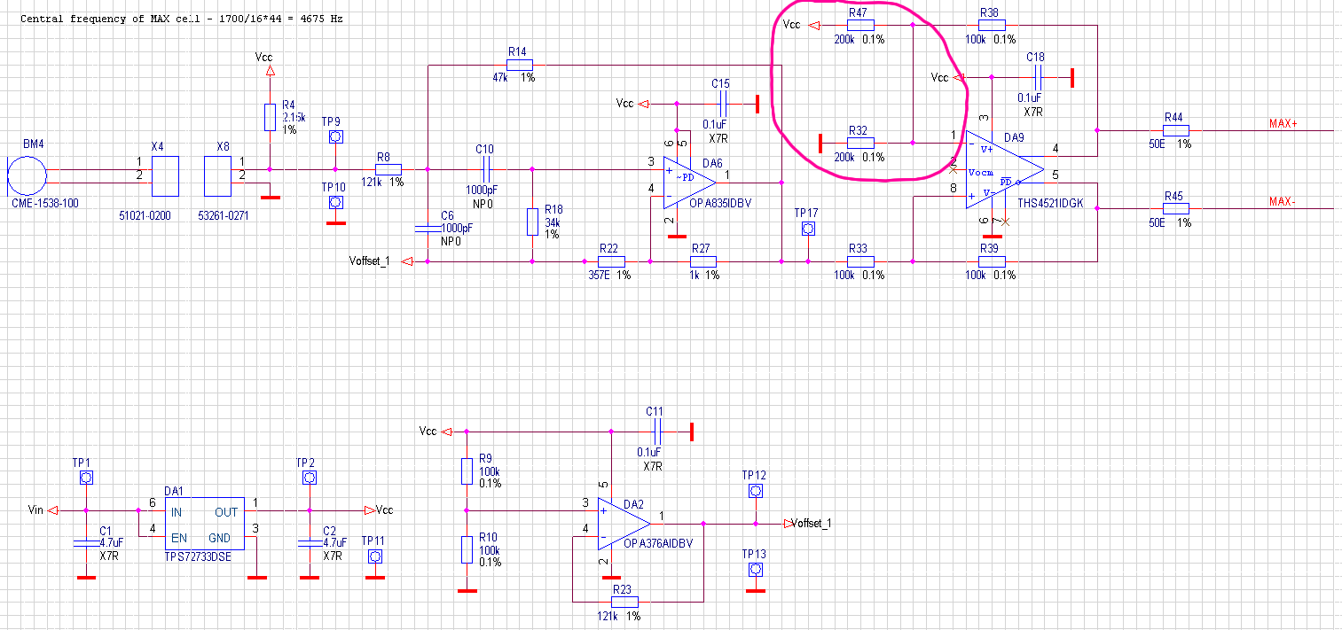
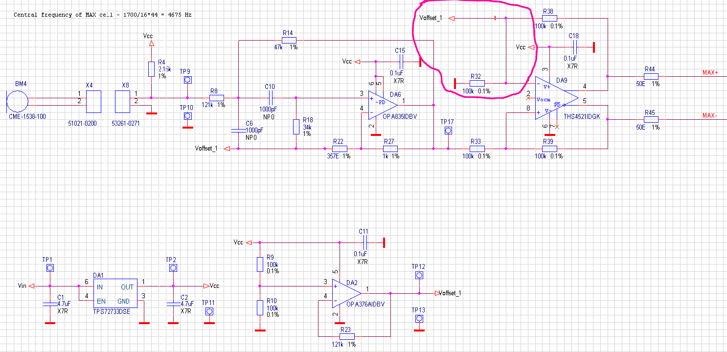
Filter params: fo:4700Hz, BW:1kHz, gain=5, Q=4.7, one stage (2nd order), LinearPhase_05, SallenKey topology.

So, FilterPro gives me a requirement for min GBW of opamp as 11,045 MHz. Why GBW must be so big? Frequency is in audio area... it seems to me, that 11MHz is too great, am I not right? What is the equation for min GBW calculation?

Thanks a lot in advance.

  • Hi Maxim,

    Indeed the result you have received from FilterPro regarding the minimum GBW requirement although surprising, is justifiable and correct. It is the summation of all the filter requirements that force a higher than expected gain-bandwidth (GBW) even though individually each requirement doesn't appear to be very demanding.

    Not apparent is the fact that the open-loop gain (Aol) must be at least 40 dB (100x) above closed-loop gain (Acl) to keep the filter's gain error less than 1% at the filter stage's natural frequency (fn). Therefore, the minimum GWB is approximated by FilterPro from the relation:

    GBW(min) = Fn x Q x ACL x 100

    which for your filter is (4.7e3) (4.7) (5) (1e2)  = 11.045 MHz. The result that FilterPro returns. The 100x is the 40dB gain above the closed loop gain of 5x.

    You can compromise and use an amplifier with lower GBW, but you will notice that the gain, fn, phase and group delay accuracies will all begin to deviate from the more ideal responses the lower the amplifier GBW is moved downward.

    Many of TI's CMOS and bipolar operational amplifiers have a GBW specification of 11 MHz, or higher, and still have low power consumption. If you would like assistance selecting an amplifier that meets your filter's requirements we would be happy to help.

    Regards, Thomas

    PA - Linear Applications Engineering 


  • Thank you, Thomas.

    Exhaustive explanation.

    Relative to opamp selection. If you will help me with this problem - it will be great. 

    I'm designing a filtering amplifier for laser optic-acoustic cell. I've selected an ECM, so I need to built a filter-amplifier for it. Opamp requirements are: Vcc =3.3V, RRI-RRO, Low noise (<220uVp-p, <10nV*sqrt(Hz)), Low power (active current <1.5mA), GBW (from FilterPro) > 11.045MHz. 

    Cell contains four stages, so, for 3 of them I've selected OPA376 (fo in that stages is 1700Hz, => min GBW 2,4MHz). But opamp selection for fourth stage is a problem :(. There are three candidates: OPA835, OPA1662, LMP7731. Could you comment my choice or help me with opamp selection.

    Thank you.

  • Hi Maxim,

    Any of the three amplifier models you have identified for the fourth amplifier should work well that application. I am most familiar with the OPA1662, of the three models. It meets all the requirements and has the very low 3.3nV/rtHz voltage noise performance. The OPA835 is a high speed operational amplifier and has very good performance relative to the application. It is a very fast amplifier so layout and component selection may take a little more care. The LMP7731 also has very good performance specifications, but does have a much lower slew rate than the other amplifiers. That may, or may not be an issue in your application.

    One other operational amplifier I would like to recommend for the 4th amplifier is the OPA320. It meets all of your electrical requirements. Also, it is available as a dual device, the OPA2320. You could use 2 of the OPA2320 and easily cover all 4 stages. Similarly the OPA1662, also a dual device, could be applied in a similar manner.

    Regards, Thomas

    PA - Linear Applications Engineering


  • Thanks a lot, Thomas.

    One more question, this time - about FDA application. 

    Sorry, may be it's stupid question, but... Could you explain me what issues may appear, when I'll use schematic #2. Application docs shows, that best way is sch.#1 - Tevenen scheme - balanced, good... but in this case offset on IN- pin of FDA and Voffset may be different - according to resistors tolerance, but in 2nd variant offsets on OPAmp and on FDA are definetely the same. What conclusions may occur in this variant?

    Var1:

    Var2:

    Thanks.

  • Hi Maxim,

    The THS4521 is supported by the E2E High-Speed Amplifier's forum and they have expertise with the FDA roducts, but I will provide some feedback based on my review of your circuits.

    • The second circuit benefits from the inverting input being referenced to the same voltage Voffset_1 as the non-inverting input. That takes the errors associated with the Vcc level and R47/R32 tolerances out of the equation. However, I do believe the low end of R32 should be connected to Voffset_1, not ground.
    • I suspect that the resistor values selected for the input and feedback resistors R32, R33, R38& R39, that are being used with the THS4521, are too large in value. This has implications for both the dc and ac performance of the circuit. The datasheet shows most circuits having a 1k feedback resistor value. Datasheet page 22, table 1, provides recommended values for the feedback and resistors based on the stage's gain requirement.
    • Do not put resistor R23 in the feedback of DA2, the OPA376. There is no need for the resistor and it increases the likelyhood of instability. This large resistance in conjunction with the amplifier input capacitance adds a pole in the feedback loop that degrades the stage's phase margin.

    I hope this helps!

    Best regards, Thomas

    PA - Linear Applications Engineering


  • Great thanks, Thomas.

    In the future I'll try to be more accurate  - so large bias current (~1uA) of THS4521 was a surprise for me. Surely, values of resistors must be lower than I placed in schematic.