This thread has been locked.

If you have a related question, please click the "Ask a related question" button in the top right corner. The newly created question will be automatically linked to this question.

FVC110(500KHz-Full Scale)

Other Parts Discussed in Thread: VFC110

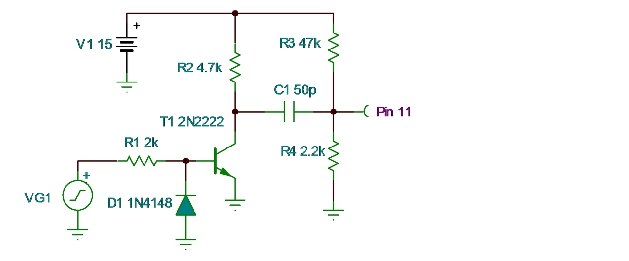
Currently I am developing a Frequency to Voltage convertor(500KHz Full scale) using VFC110. As follow on datasheet,using the given application connection Frequency to Voltage (Figure 4,pg 9).


Using Rin;58kΩ, Cos;330pF, Cint;2nF

Pin 10; 15V(+Vs) with 1nF(coupling cap)

Pin 4; GND(-Vs) with 1nF(coupling cap)

Pin 2,3,5 & 8; N.C

Pin 13,14 & 7 ;GNDAnalog gnd share the same gnd.

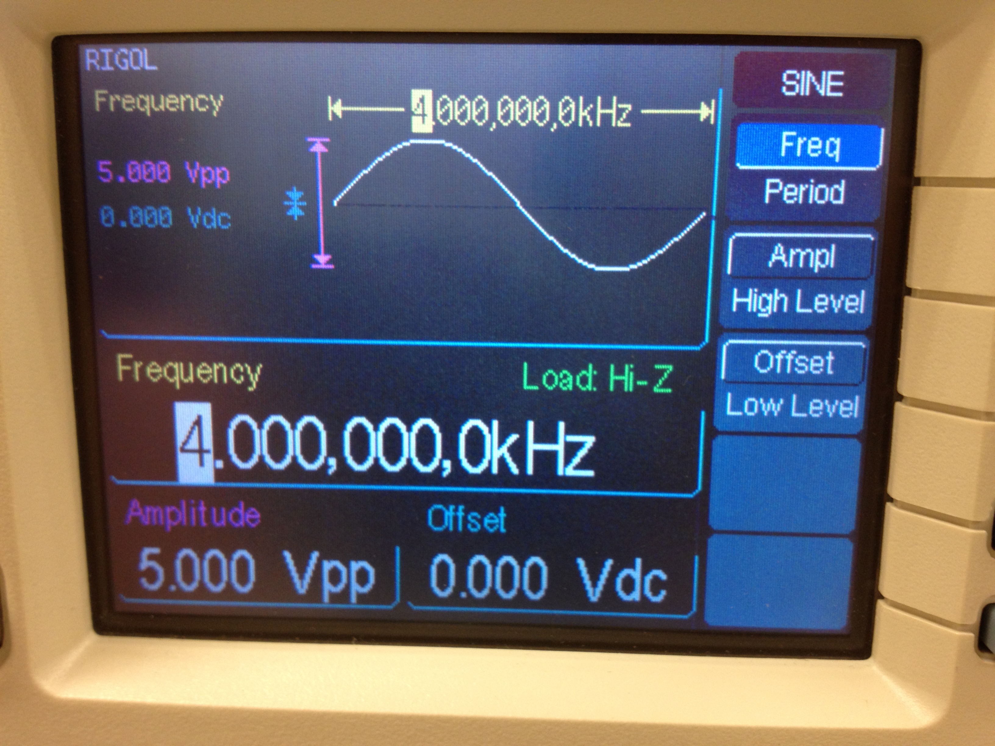
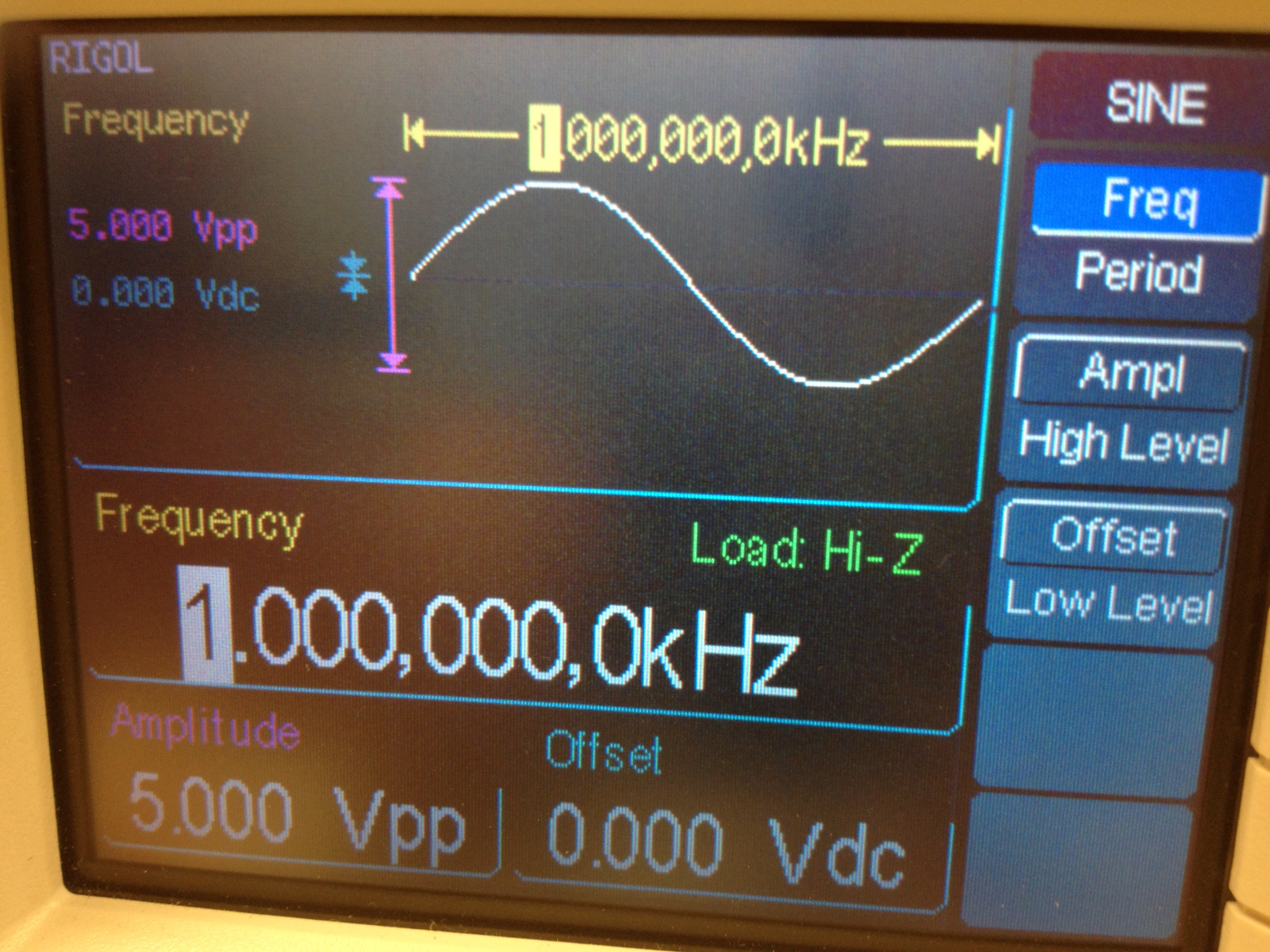
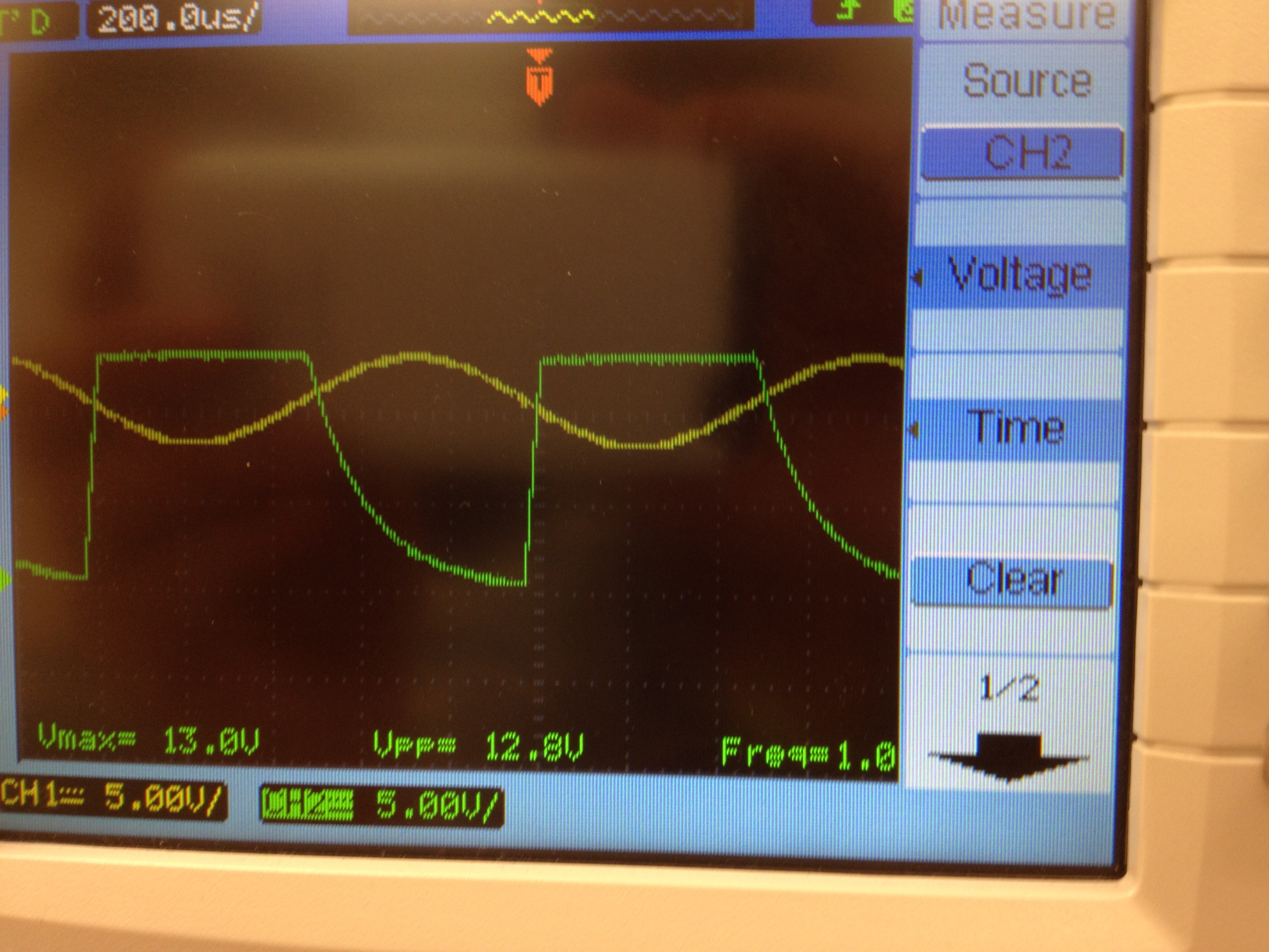
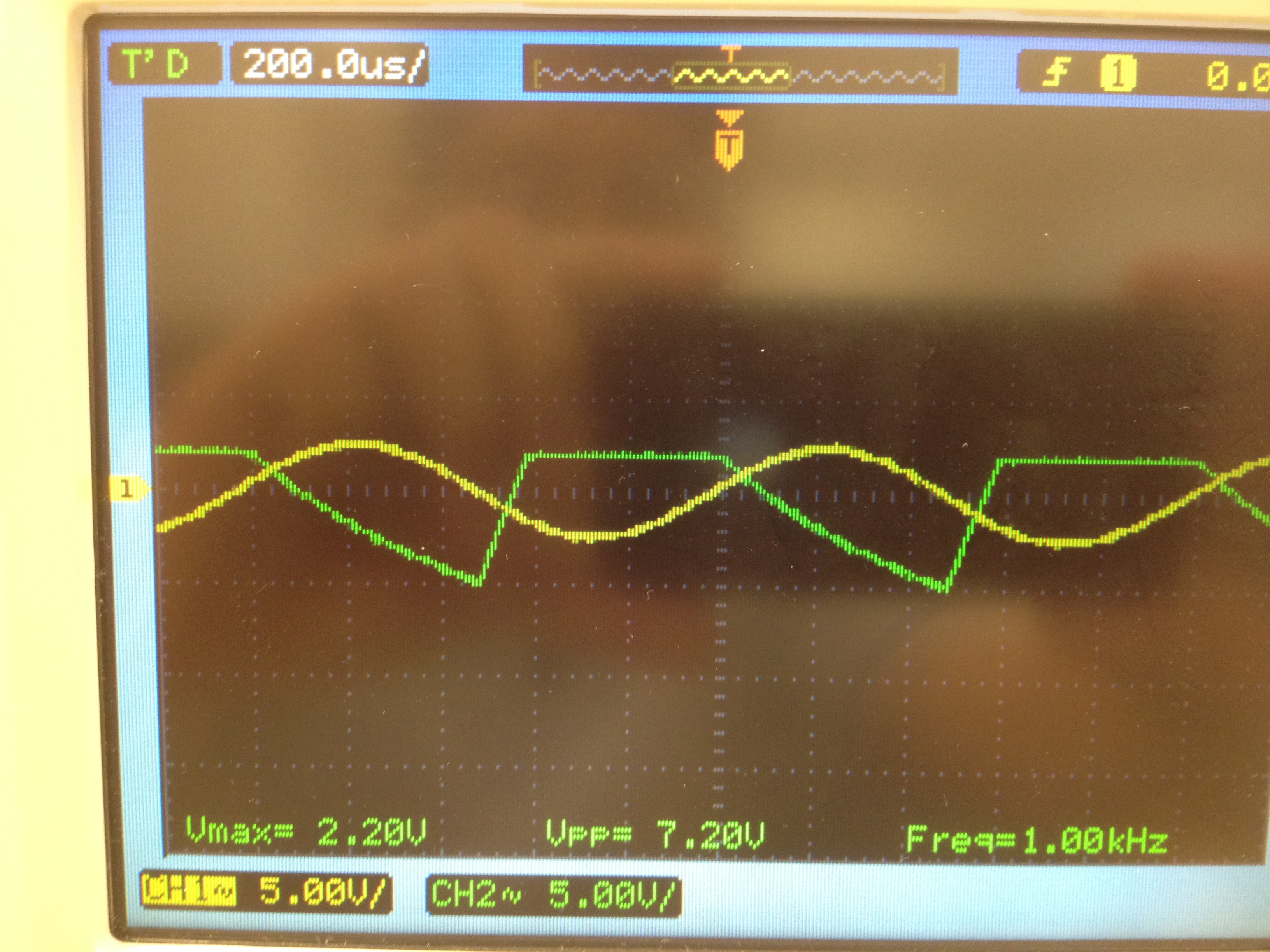
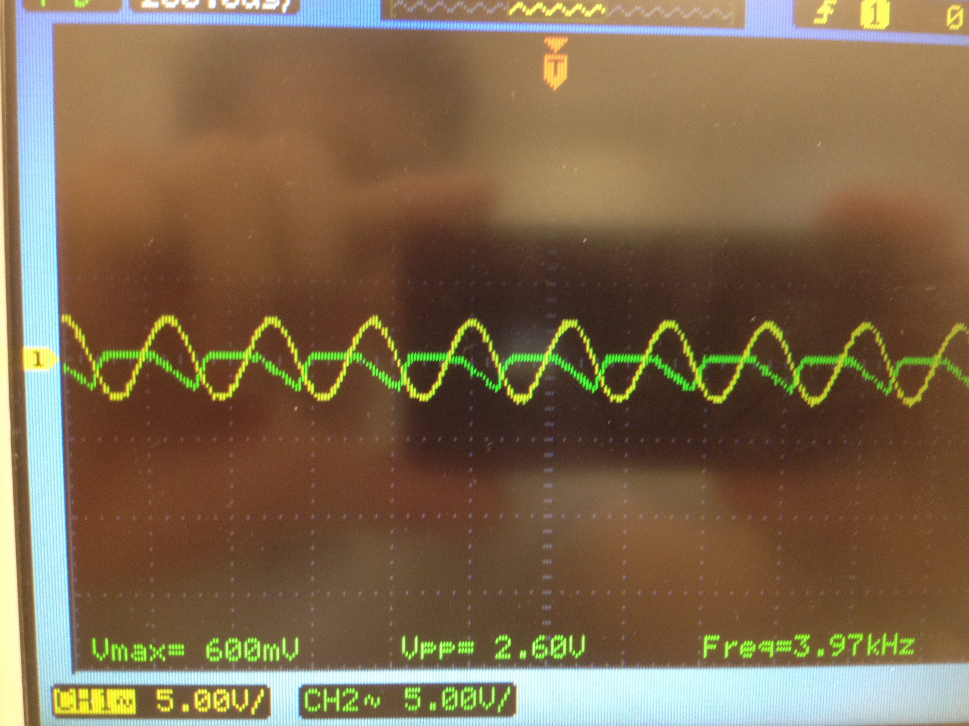
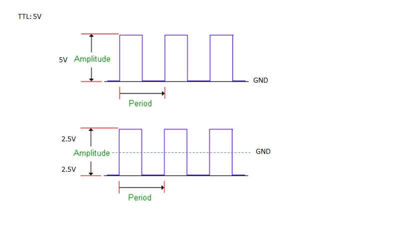
Pin 11; Use only positive voltage(+Vs) + Long Pulses Fin; Sine wave 100KHz with 5Vpp


Outcome:

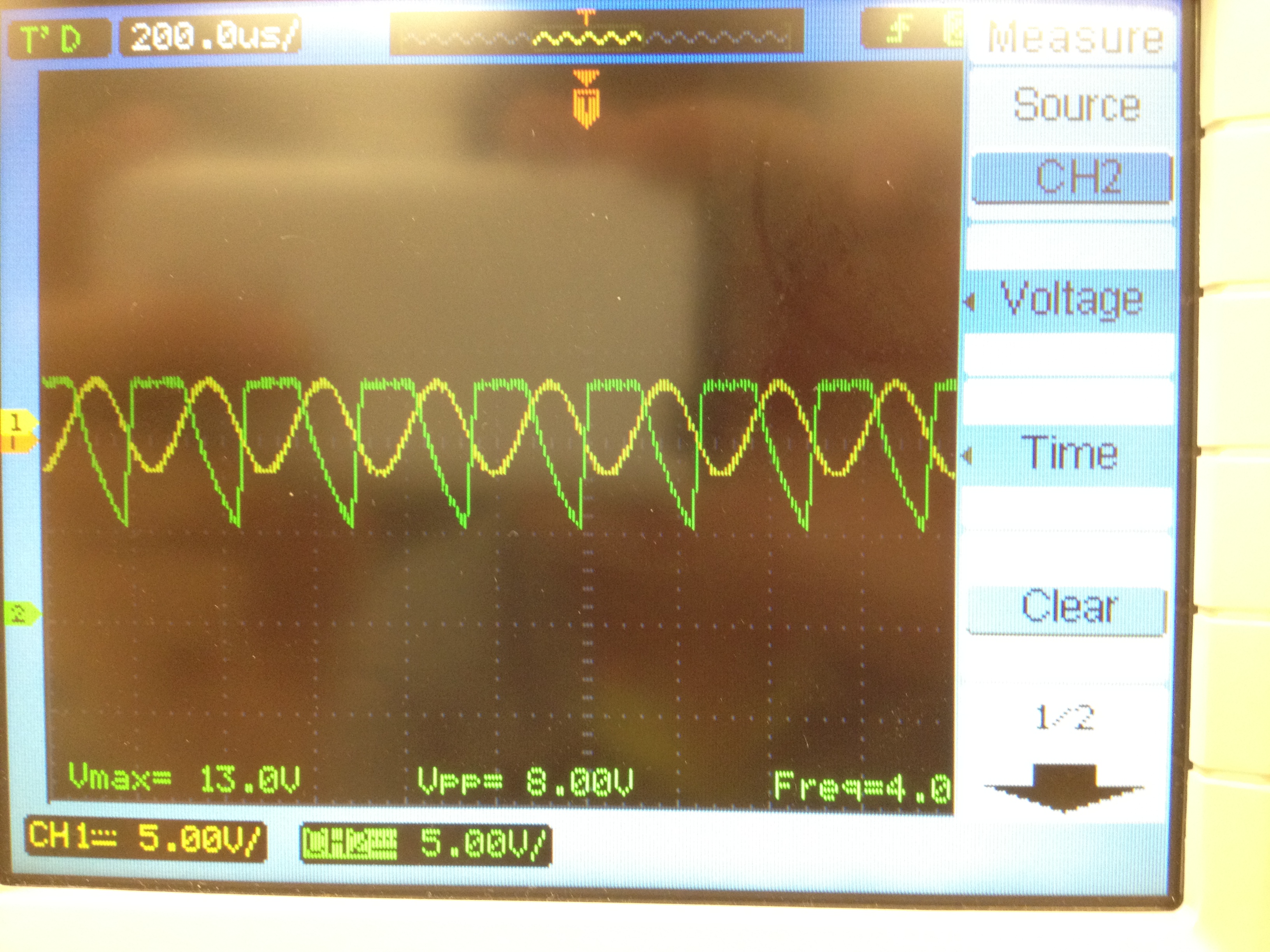
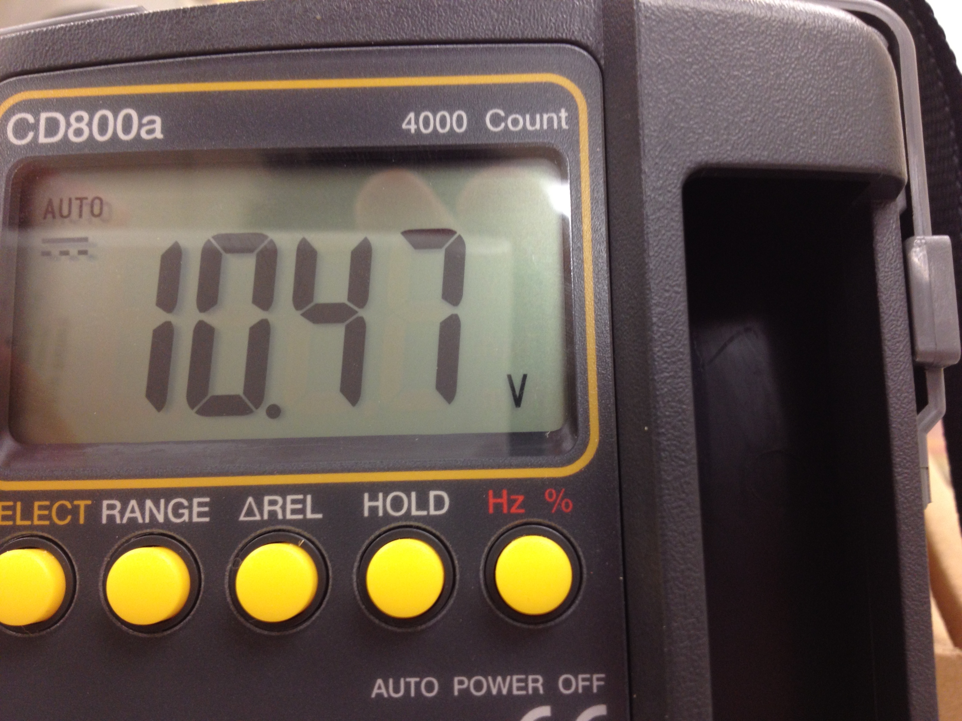
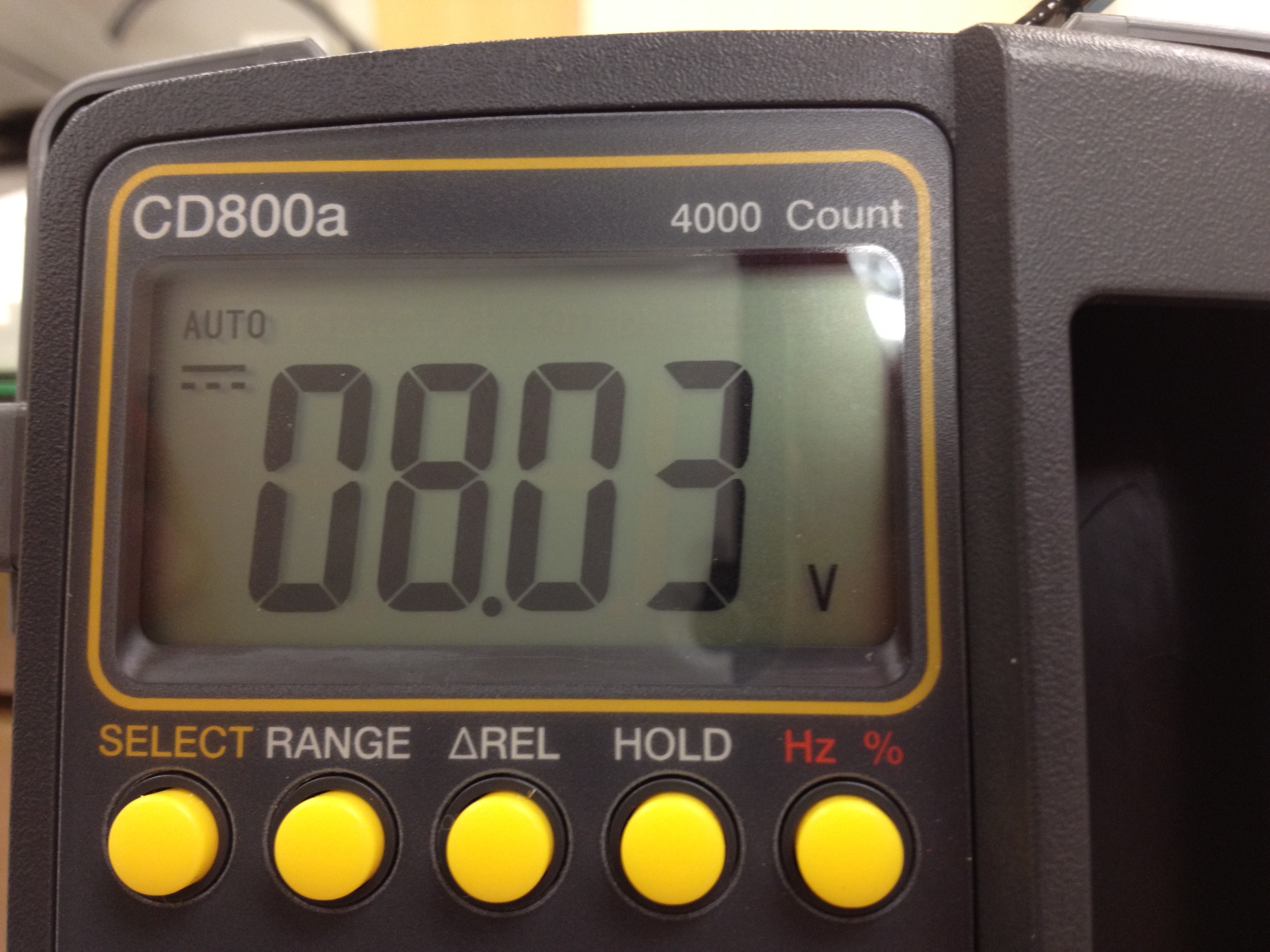
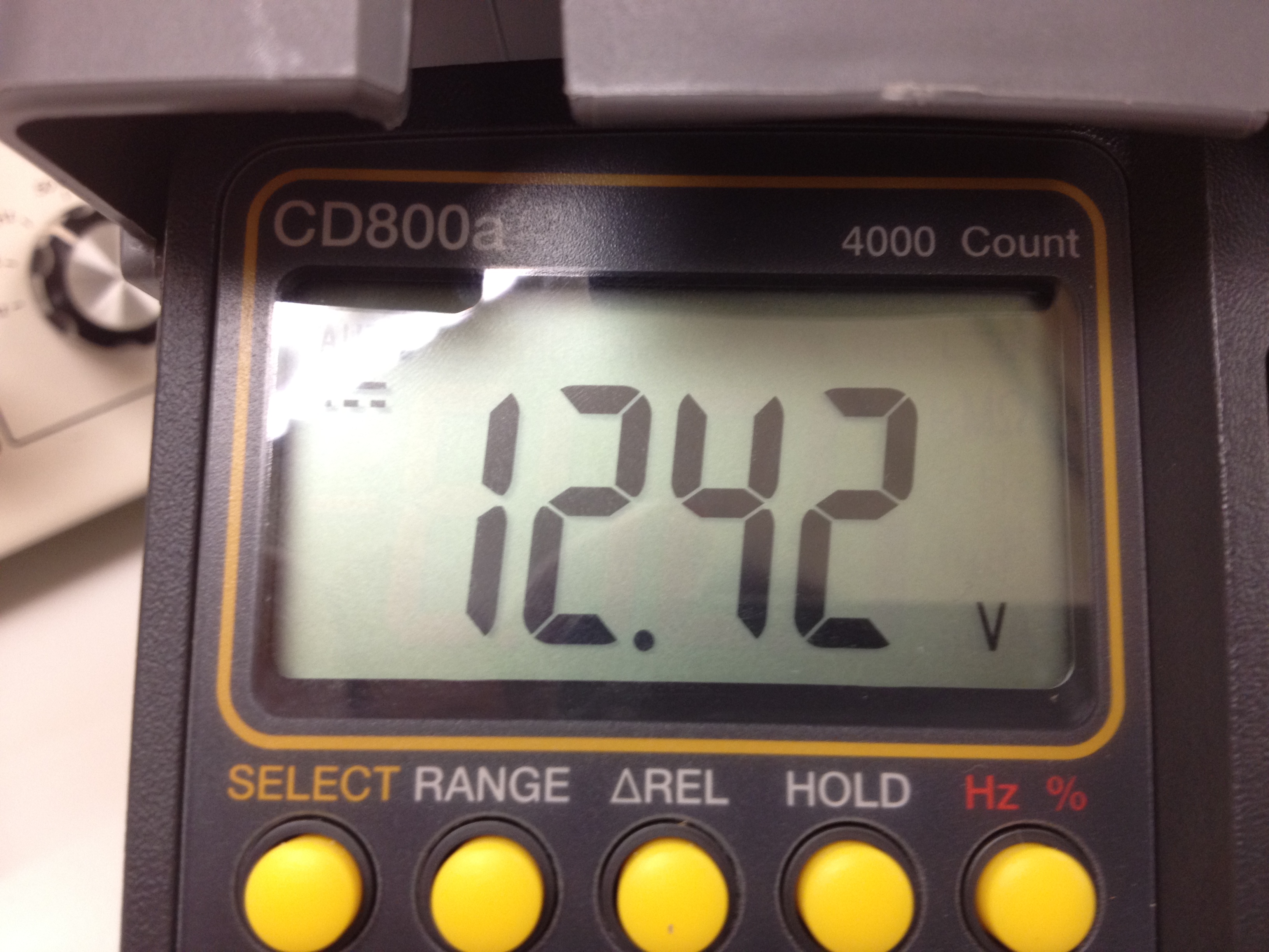
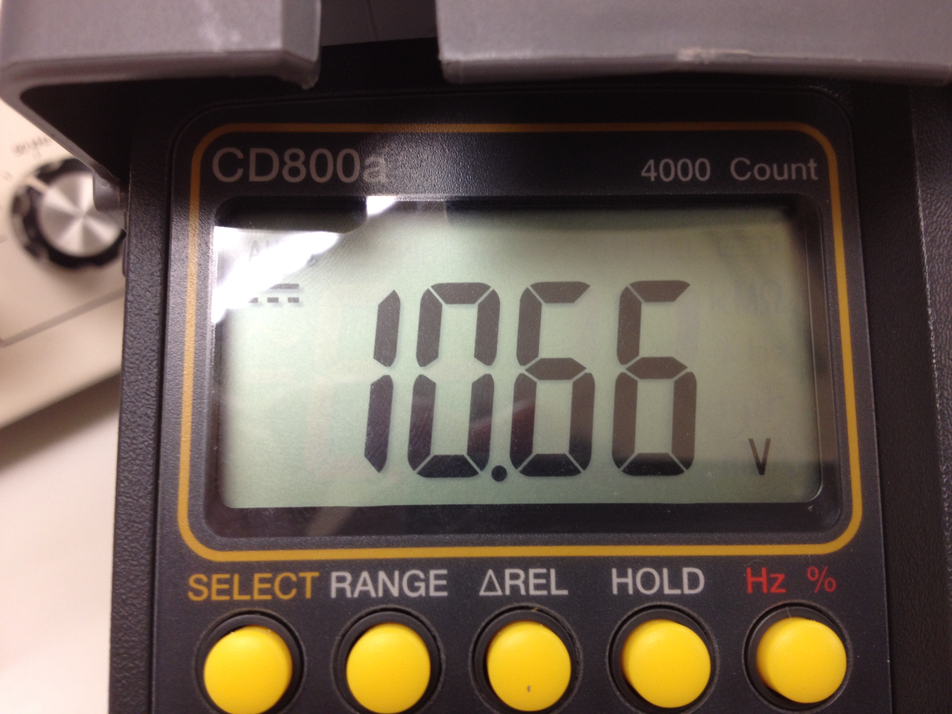
Frequency 100KHz=113mV Frequency 500KHz=109mV


Enquiry:

What is the actual voltage value for 100KHz and 500KHz?

What is the input setting for the signal generator (Vpp,Vrms,Offset) ?

Will it be OK, if didn`t connect (-VS) ?

What is "one-shot" function inside the VFC110 ? ]

  • Sky,

    The VFC110 requires a negative power supply voltage on the -Vs pin of at least -8V. Generally a +/-15V power supply is used for this device.

    The output voltage with the values you are using should be approximately 10V at 500kHz input and 2V at 100kHz input.

    The input frequency is assumed to be 5V "TTL-compatible" pulses. 3.3V logic will also work. I recommend using the capacitive coupled input circuit shown in figure 4 as it reduces concerns about the low-period duration of the pulses. See the text on frequency to voltage conversion for an explanation.

    The one-shot is a timing circuit that determines the duration that the internal current source switch is closed.

    Regards, Bruce

  • Bruce,

                Thank for the solution and detail explaination, it`s help and working. But I noticed the output from the Frequency to voltage converter is not a pure D.C.

    How can I use this output, to input to the ADC to do conversion?


    For 4KHz


    For

  • Sky,

    To decrease the ripple in the voltage output, increase the value of Cint. This will not change the average DC output voltage but will reduce the ripple. This capacitor can be increased without limit to reduce the ripple as small as you would like. It will, however, affect how fast the output  voltage will respond to a change in frequency.

    Regards, Bruce.

  • Hi Bruce,

                    Thanks, the ripple have become small but average DC output is not the same as previous. Change only Cin (Previously Cin=2.2nF Present Cin=10nF). Please advice.

    Do you have any idea how this FVC output work with Microcontroller ADC( PIC18F4520) ?

     For 1KHz


    For 4KHz

  • Sky,

    A sine wave cannot be used directly as an input in f/v mode. The comparator input on pin 11 must not remain negative for more than approximately 1/10 / fmax. See the small diagram in figure 4. You can use a square wave with the upper capacitively coupled circuit. A sine wave input with this circuit will not operate properly.

    Are you able to provide a square wave input? If not, I can provide a simple transistor interface circuit that can accept a sine input.

    Regards, Bruce.

  • Hi Bruce,

                    Thanks, please show me the transistor circuit on how to convert the sine wave to sqaure wave. I still a bit unsure above the input format for the F/V, I need to apply a TTL 5V square wavform or a logical "1" to make the F/V function? Is it either this 2 format is correct?


  • Sky,

    Here is a circuit that will convert a sine wave into the necessary pulses to be connected to pin 11. It requires a ground-referenced sine wave input of 2Vpp or greater.

    Regards, Bruce.