This thread has been locked.

If you have a related question, please click the "Ask a related question" button in the top right corner. The newly created question will be automatically linked to this question.

Updating an "old" design

Other Parts Discussed in Thread: PGA202, PGA103, INA128, ADS1259, PGA280

Hello,

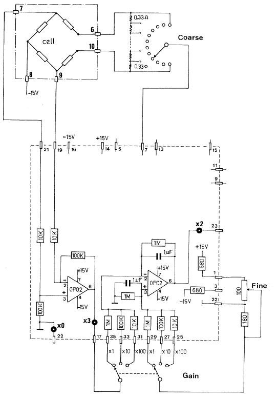
In an "old" design made in 1987 (this design is still used and if correclty set, works well), a Wheatstone bridge is used as a measurement cell (a current source supplies the cell by the pin 7 of the board) with a first amplifier with a gain of -10 and the second is used with a manual selector to set the gain between -1 to -100, giving a global gain from 10 to 1000. We measure the output voltage on the point x2. I consider that my level in analog is quite poor (I'm more involved in microcontrollers programming... sorry) but I hope that my understanding is correct for the moment.

I'm thinking (maybe I'm wrong) that using an unique programmable gain instrumentation amplifier (as PGA202 or another) should make the job of the two OP02 (if we do not pay attention to the filter on the second OP02) and maybe better because the common mode rejection would be better with the PGA202 than using the OP02 with all resistors (now we can achieve a noise of 20µVpeak-to-peak with the global gain of 10 on X2). I'm also thinking that the global gain of the design will be more "repeatable" with the PGA than using 2xOP02 + resistors.
Can you confirm that this idea is correct or not (with simple explanations, please) ? I would like to make other changes but I would prefer to do it step by step if it's possible. I hope that I do not forget to provide all needed information.

Best regards,

  • Sebastien,

    Your goals are not fully clear. I'll assume that you want to keep using the same supply voltages. Can you describe the circuitry that you are driving at x2?

    The PGA202 is not well-suited to the application. I would suggest a possible signal chain of the INA128 set to a gain of 10, followed by the PGA103 with programmable gain of 1, 10 and 100. This would provide the same gains as your present circuit using two digital control pins. This would require only one precision resistor on the INA128 to set the gain of 10.

    The data sheets for these products show the basic connections. Your circuit should be simple to implement. The present circuit has a very low frequency cutoff, below 1Hz. This could be implemented with R/C filters between the two stages and at the output.

    Regards, Bruce.

  • Thank you Bruce for your answer.

    The X2 is connected to a potentiometer used as a voltage divider (used to set the global gain/sensitivity suited to the requested application) which is connected to an ADC 22bit Delta-Sigma, (currently from another manufacturer, the ADC is also old and difficult to find) with an input range of +- 2.5V.

    If we use the gain of 1000 at X2 and divide the output voltage by a factor of 5 to achieve a gain of 200 (it's just an example of a possible application, to have the maximal sensitivity and to prevent saturation of the ADC), final gains will be 2, 20 and 200, which can be not suitable for another measurement that the sensor would be able to perform with a higher gain. Of course, it would be possible to adapt the resistors of the second stage but adapting each resistors for each application...
    One of the goals would be to add more flexibility of the gain (automatic and not manual changes of the gain, making autoranging applications and so on...) comparing to the current design (as described on the figure 4 of the datasheet of the PGA103 for example).

    On the first OP02, there are four resistors used to make a differential stage with a gain of 10. If the brigde is perfectly balanced and the resistors perfectly matched, we should have an output signal close to 0V on X3. Unfortunately, it's never the case and we can have difference voltage in a range of -10mV to 10mV between pin of 19 and 21 (even with the manual addition of the 0.33ohm to balance the bridge). Because the range of the ADC is +-2.5V, it's not always possible to use the gain of 1000.
    Is it correct that using the INA128 + PGA103 should also reduce the gain error comparing to the resistors, giving maybe a more "repeatable" gain on each board ?
    Another point that I'm concerned (maybe I'm too much concerned or completely wrong) is the effect of the resistors of the first stage on the common mode voltage.
    Can we assume that with the current design, if the voltage is equal on pins 19 and 21, the OP02 will really provide an output voltage close to 0V on X3 and can we assume that we will have "the same behaviour" if common mode voltage is totally different ? I suppose that the matching of the resistors will also affect the measurement.
    I was thinking that using an instrumentation amplifier as the recommended INA128 will help to achieve better performances to remove common mode voltage.

    Another goal will be to be able to make "an automatic compensation" of the offset of the cell itself measured on pin 19 and 21 during a specific period of time (maybe with a DAC ?) and depending on the voltage needed to compensate the offset, determined if the cell is used/working correctly. This compensation would be also used to remove the manual selector of the 0.33ohm resistors. Another point is the power supply of the bridge (currently 7815 and 7915), I was thinking that using a low noise voltage reference driving the base of a transistor may be used to supply the needed current on the bridge (about max. 200mA for the full bridge) ?
    But for the moment, if it's possible, I would prefer to focus on the two stages to clarify all these points before talking about automatic compensation or possible improvement related to the power supply.

    Best regards,

    Sébastien

  • Sebastien,

    It appears that you may need to redesign the whole system, including data converter. Consider the PGA280 + ADS1259. These two devices are designed to work together to make a very versatile, programmable signal acquisition system. It provides a wide range of input gain and high resolution conversion and versatility to address possible future needs.

    Regards, Bruce.

  • Dear Bruce,

    The parts had been ordered and will be tested soon.
    Just for my information, is there some applications where PGA + ADC are recommended instead of using an ADC with an internal PGA ?

    Best regards,

    Sébastien

  • Sebastien,

    It's all about performance and features. There is no fundamental disadvantage in a combined part. Separate PGA and ADC may provide greater choices and versatility.

    Bruce