This thread has been locked.
If you have a related question, please click the "Ask a related question" button in the top right corner. The newly created question will be automatically linked to this question.
Hi,
I'm evaluating the new stellaris cortex m4 to use it for a redesign of our industrial control.
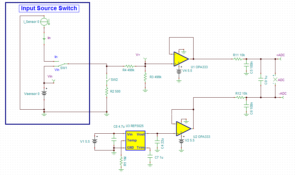
So I would like to ask you analog experts what is the optimal solution for converting a 4-20mA industrial pressure sensor (or optional output 0-10V)
for the ADC of the TI Stellaris?
Can an application node and /or reference design be found on this site?
Is there maybe already a plug&play solution to attach on the MCU's ADC?
I would be very happy for your answer
kind regards
Ersan
Ps. at the moment we are using a 160Ohm Shunt Resistor :( and a optocoupler (not my fault, im new to the company)
Hi Ersan,
I have something similar to what you're looking for. Here is a simple circuit powered from +5.5V that will translate a 0-10V signal or a 0-20mA signal into a 0-5V signal for the ADC. By using a +2.5V reference you will use the full range of the ADC. You can modify the resistor divider values and reference voltage levels to accomodate for different ranges if desired.
Regarding your dislike of the sense resistor, it is actually very common to simply use a resistive load for the 4-20mA receiver as your company currently does. What are your reasons for wanting to do it a different way? (less voltage drop, less power loss, etc.)
Hi Collin,
thank you very much for that nice application draw.
Actually you've been right with your guesswork about energy consumption.
I thought the industrie is using a all in One Chip solution with integrated reference volate and optocouplers.
I will try to build up your solution it seems very easy and solid.
Is the ADC of the Stelarris 5V tollerant? I thought the max is 3,3V.
Thank you very much!
Hi Ersan,
We don't have an "All-in-One" chip like the one you've mentioned, sounds like it would be a neat part though.
I'm not sure about the ADC in the Stellaris processors, but if it is limited to +3.3V then you'll have to scale things differently with a different resistor divider and reference voltage.
hi dear
i want to use the circuit .can we give these to signal +adc and -adc to adc +signal and -signal direct
will it work?
Hello Saurabh,
The solution shown a few posts back was designed for a +5V ADC input. If the input voltage to your ADC is different then you'll have to scale the output and reference circuit accordingly.
you can't use the circuit 1:1 it's much more complex becaufe of load on in & outputs, protection and much more....
this circuit show just the basic princip of how it could work.
Maybe someone point out to a link to a industrial ready to use 0-20ma / 4-20ma sensor input circuit. but because it's know-how no one would do that.