This thread has been locked.

If you have a related question, please click the "Ask a related question" button in the top right corner. The newly created question will be automatically linked to this question.

LMV7219 comparator input impedance?

Other Parts Discussed in Thread: LMV7219, TINA-TI, LMH730316

I need a comparator LMV7219 as a sin to CMOS converter. Generator’s output signal is 450 mV (amplitude) at the 10 K load.

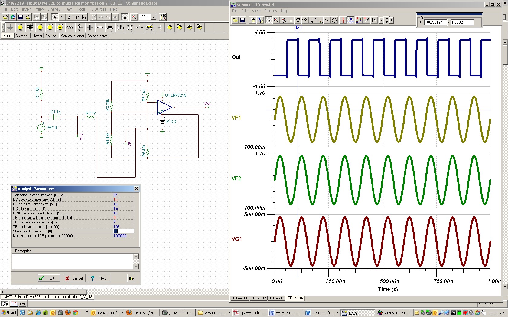
I made a circuit (please, see attach "Circuit 3").

It is known, that can not apply a voltage less than minus 200 mV to the input of the LMV7219.

At the same time, the generator’s load must be within 8-11 K (otherwise frequency stability can not be guaranteed). If I set R1 equal to 5K , the Um2 voltage is 100 mV. If I set R1 more than 20K , the LMV7219 doesn’t work at all. The value of the R2 is almost no effect on the Um2.  R1 and R2 were 100 K each first, but the comparator does not switched at all until I significantly reduced the R1.

I can not understand, is the input impedance of the LMV7219 at 10 MHz is only a few kiloohms (or even less)? But there must be at least 50-100 kiloohms! In the LMV7219 datasheet input impedance is not specified. Сircuit assembled on a printed circuit board, the distances between the elements are minimal.

Can I somehow estimate the value of the load of the generator, provided that I know R1 value, Um1 and Um2?

 I modeled in the TINA-TI program and used the oscilloscope - TINA-TI gives the result as if the input impedance of LMV7219 is large, and all supposedly determined only by the ratio of resistors R1, R2. But the real results do not like the program. I used a broadband oscilloscope and probe with a divider 1:10. Perhaps the reason is that the signal comes into the negative region? Maybe, it makes sense to tie each input of LMV7219 to the potential of 1.65 V using a resistors dividers to 200 kilohms? Please, see attach. comparator.vsd.

6545.28.07.2013_comparator.vsdTIA

Vladimir Naumenkov

www.agat.by

Circuit 3.pdf
  • Hi Vladimir,

    I understand that you are getting less than expected swing on the + input of the LMV7219. I'm curious to know if the swing is any higher at lower than the 10MHz frequency you are testing (say 1MHz)? If so, this could be related to your 10kohm resistor(s) and input / board capacitance in the pF range? I don't know if you have the capability of testing at lower frequency or not? You may want to use a bench generator and lower value resistors, just for testing purposes.

    I like the idea of your *.vsd file (where you are biasing the inputs to approximately mid-rail for your detection). That is much better than operating at 0V CM level and being limited to -0.2V at room temperature (and even less at 85 deg. C). However, I have some comments:

    1. It is best that you choose your external divider resistors so that the - input is biased to ~1.2V to take advantage of the full CM voltage range (-0.2V to 2.3V with Vcc= 3.3V). So, you could readjust R4, and R5 appropriately (e.g. R5= 24k, R4= 42k).

    2. The input bias current could be as high as 2uA over temperature. So, I'd choose your resistors lower to reduce the error. In #1 above, I've lowered the resistors for that reason.

    3. I'd eliminate R3 (0ohm) and replace R1= R4= 42k, and R2= R5= 24k for balance and to cancel the input bias current error. If necessary, you could also eliminate / adjust-higher "Rload" (since R1|| R2 is already a 15k load).

    Regards,

    Hooman

  • Dear Hooman,

    Thank you.

    1)Please, answer, how do you think, what would be the approximate value of the input impedance of the LMV7219 at 10 MHz if inputs is biased to ~1.2V (not counting the resistance of resistor dividers)? 

    2) I modeled  comparator.vsd circuit in TINA-TI, and I set R1= R4= 42k, R2= R5= 24k. TINA-TI all shows beautifully, the LMV7219 operates("GOOD#1" figure). Then I slightly adjusted the circuit: I feed the signal generator( in TINA-TI of course) to "-IN" (the thing is that, on my PCB all very closely and convenient to make changes in this manner),  and, when I run the oscilloscope, I get the message "operating point is not defined" ("Error" figure). Then I (in this adjusted circuit) set R1= R4= R2= R5= 42k and LMV7219 works  in TINA-TI ("GOOD#2" figure). Why?  Are  "-IN" and "+IN" inputs not equal? (Please, note: numbering of resistors in comparator.vsd differs from docx files and TSC files.)

    I started to gradually increase the "24k resistor" values ​​on 1 kilohms, and at values 28k adjusted circuit work too in TINA-TI ! (please, see attach TSC files)

    6443.comparator.vsd

    1351.GOOD1.docx

    4846.GOOD2.docx

    3125.Error.docx

    1777.LMV7219 Test Circuit3.TSC

    2262.LMV7219 Test Circuit5.TSC

    5040.LMV7219 Test Circuit6.TSC

    TIA

    Yours sincerely,

    Vladimir Naumenkov.

    www.agat.by

  • Hi Vladimir,

    1) LMV7219 Input Impedance: Unfortunately I don't have the input impedance values of the LMV7219. We could try and measure it for you by next week.

    2) TINA-TI issue with -input drive: I can also see your issue with swapping the input being driven. I can solve the error issue when driving the -input by changing the analysis settings.

    I went into TINA-TI, Analysis, Set Analysis Parameters, Shunt Conductance and changed it from 0 (S) to 1p (S) instead.

    I think this has to do with the conductance assumed by TINA-TI from open circuit nodes to ground (but I'm not 100% sure about it). Regardless, that allows the simulation to run! I've heard about Pspice convergence problems before and the fact that these analysis settings affect that.

    Here is the image showing what I changed and the successful run to the right:

    Here is the modified TINA-TI file:

    2728.LMV7219 -input Drive E2E conductance modification 7_30_13.TSC

    Regards,

    Hooman

  • Dear Hooman,

    Thank you.

    Yours sincerely,

    Vladimir Naumenkov.

    www.agat.by

  • Hello Vladimir,

    I've made some input impedance measurements for the LMV7219 (Vs=5V):

    • Rin = 750kohm
      • Calculated by measuring the input 1kHz sine wave amplitude drop / voltage division through a 93kohm series input resistance
    • Cin= 2.3pF
      • Calculated with varying the input series resistance (0ohm and 5.5kohm) and measuring the change in output transition time (8.7ns change) and back calculating the input RC time constant to arrive at the total input capacitance

    The input capacitance Cin includes the board (LMH730316) and of course the device package (SOT23-5).

    Let me know if you need any other information?

    Regards,

    Hooman

  • Dear Hooman

    Thank you

    Please, answer: as Generator must be loaded at 10k, then I made calculations, please see attach. So therefore, I still need to install R3=5.3k? I ignored the value 750k.

    Sincerely yours

    Vladimir Naumenkov

    www.agat.by

    4111.Comparator_09.08.2013.vsd

  • Hi Vladimir,

    To make sure the generator sees a 10k load at the 10MHz frequency, and using the measured LMV7219 input impedance:

    Your approach has a slight error in that you had assumed the Cin (2.3pF) impedance as a pure resistance in your computation and ignored its phase angle. I've used complex arithmetic in Excel in this attachment and calculate a value of 5.58k ohm for R3 (instead of your 5.3k value) to get 10k total generator load impedance at 10MHz. I used Excel, "Data", "Solver" to find the value of D4 cell to arrive at 10k in cell L4.

    Here is the spreadsheet:

    1323.LMV7219 Input Impedance 8_8_13.xlsx

    Regards,

    Hooman

  • Dear Hooman

    Thank you

    Sincerely yours

    Vladimir Naumenkov

    www.agat.by