This thread has been locked.

If you have a related question, please click the "Ask a related question" button in the top right corner. The newly created question will be automatically linked to this question.

LMH6624 High gain trans-impedance noise

Other Parts Discussed in Thread: LMH6624, TINA-TI, LMH6629


 Dear colleagues,

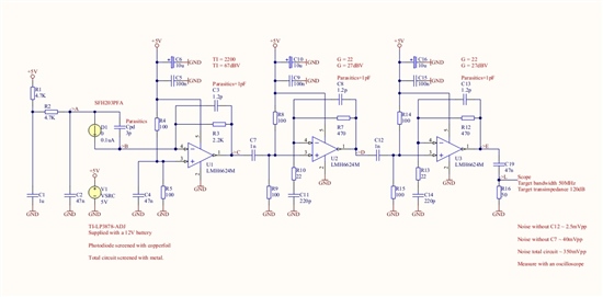
I've been experimenting with a High gain Optical receiver circuit based on three of  LMH6624 amplifier stages. The first LMH6624 stage is configured as a TIA. According to my measurements the TIA stage generates approx. 660uVpp noise, causing a noise level of approx. 350mVpp on the output of the circuit. Based on calculations I would expect a level 10 times lower. I've included the circuit below. I would really appreciate any comments on how to improve the noise level or have my calculations verified.


With kind regards, Karel.


  • Hello Karel,

    I'd expect the 1st stage output noise to be ~60uV_RMS based on your conditions and the LMH6624 noise specs (computed with TINA-TI) or about 360uVpp. So, you are apparently measuring approximately double that (or 600uVpp). I'd imagine that this was measurement was done with the optical receiver (3pF) in place. How about any noise contribution from the optical receiver? Does the fact that you are operating it with 5V reverse bias? (through R1 and R2) have any noise implication for the receive? What if you replace the receiver with a 3pF capacitor instead and run the noise test to see if the receiver adds any noise?

    Also, is there any way for you to make sure the C3 compensation capacitor (1.2pF) is the proper value by looking at step response to make sure it is not oscillatory? If the C3 value is not optimum based on your board / parasitics, you could have noise peaking (due to R3 feedback looking into Cpd of 3pF). So, it is essential that C3 value is optimized on the application board.

    Here is the 1st stage TINA-TI simulation file if you like to experiment with it.

    5775.lmh6624 Optical Receiver 8_19_13.TSC

    Regards,

    Hooman

  • Hello again Karel,

    For your 1st stage: Since the LMH6624 is stable for closed loop gains of 10V/V or higher, I believe your compensation capacitor (C3, capacitor across feedback resistor of 2.2kohm) may have to be raised lowered. You may be experiencing higher noise than expected if your frequency response is peaking due to lack of phase margin.

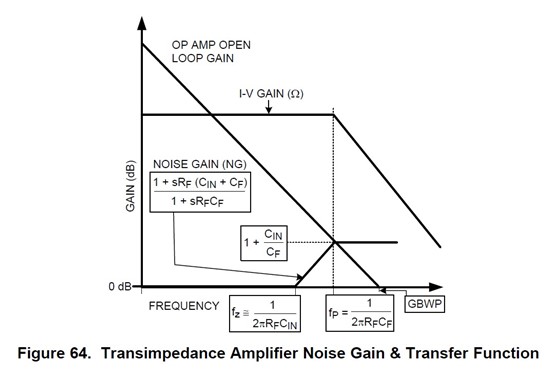
    Looking at Figure 64 from LMH6629 (shown below), if CF (C3 in your case) is too large, your Noise Gain plot will intercept the Open Loop Gain plot at a low y-axis value. For the LMH6624, this intercept should be higher than 20dB (or 10V/V). So, assuming 5pF for your Cin (3pF + other parasitic capacitances), CF < = 0.56pF (vs. 1.2pF that you have shown).

    If your CF is too low, however, "fp" would shift right and you may have instability for a different reason.

    So, I recommend you lower CF (C3 in your case) and retry the noise test.

    Regards,

    Hooman