This thread has been locked.

If you have a related question, please click the "Ask a related question" button in the top right corner. The newly created question will be automatically linked to this question.

INA156's gain on a 3-wire PT100 circuit

Other Parts Discussed in Thread: INA156, LM358A, REF200, LM358, ADS1247, ADS1118, ADS1220

Hello,

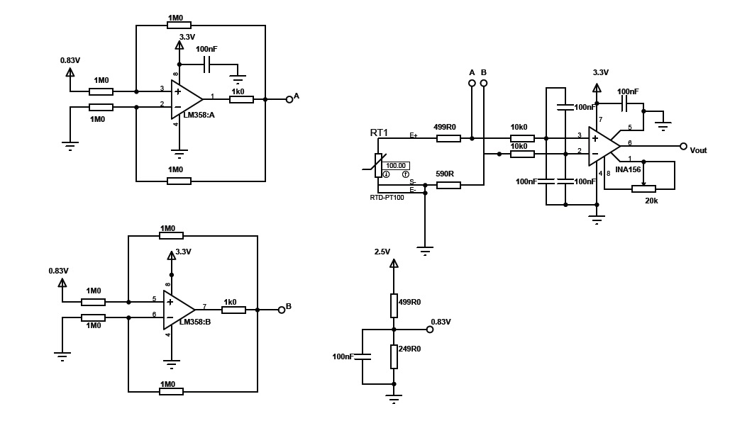
I'm using an instrumentation amplifier INA 156 in a circuit that will read  3-wire PT100 signs. Thus, the inverting input has a constant voltage level, while the non-inverting input has a voltage level close to the inverting input when the resistance of the PT100 equal to 100 ohms. 

The problem I'm finding is the  gain variation of the INA156, the gain decreases when the differential input voltage decreases. The Supply voltage is +3.3 V and ground. Ref pin is connected to ground. Gain pot is 20k.

The common-mode input voltage is 490mV, out of range [(V+) - 1.8 , (V+)  - 0.8].

What would be a solution to this problem?

Regards

  • The circuit:

    Regards

  • Hello Aline,

    Here are a few observations/recommendations:

    a) LM358A/B appear to be intended as current sources. However, I believe the feedback for the inverting terminal should be taken directly from the output of the amplifier. That would make the circuits improved Howland current pumps. Here are some reference links:

    http://e2e.ti.com/cfs-file.ashx/__key/telligent-evolution-components-attachments/00-18-01-00-00-19-28-47/Improved-Howland-Current-Pump.ppt

    http://www.ti.com/lit/an/snoa474a/snoa474a.pdf

    b) Instead of the dual LM358, you may consider the REF200. It is a dual current source that has +/-1% matching (maximum).

    c) The input common-mode voltage depends on values of the 499ohm and 590ohm resistors. Since these resistors each have their own tolerance and drift, I suggest using a single resistor connected between ground and the S-/E- terminal of the RTD. Similarly, please be aware that the accuracy of your voltage divider depends on the tolerance and drift of the resistors.

    d) I also recommend testing the circuit using a surface mount gain-setting resistor in case the parasitic capacitance of the potentiometer is causing issues.

    e) Finally, I recommend disconnecting all input circuitry and connecting a known differential signal to the inputs. Then try changing the magnitude of the input signal and calculate the gain. Beware of the common-mode voltage...you may want to supply the device with +/-1.65V or +/-2.5V.

    Here is a forum post that you may find useful.  It also notes some integrated solutions (ADS1118, ADS1220, and ADS1247).

    http://e2e.ti.com/support/amplifiers/precision_amplifiers/f/14/p/311759/1085404.aspx#1085404

    I hope this helps.

  • Hello Pete,


    Thank you for your answer!

    Turns out that the problem was the offset voltage. Since I was using  single suply voltage, it was harder to indentify (when the offset voltage was negative, the output voltage was zero). Your suggestions were very helpful!

    Also, the inverting terminal is conected directly from the output of the amplifier LM358.