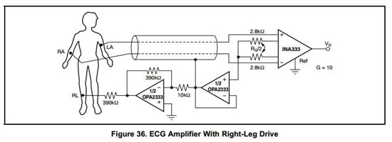
I've attached the TINA-TI circuit I've been working on. Im no expert in the electronics field or the medical engineering so I am having a hard time figuring out how to construct my ECG circuit. This signal will be connected to an Arduino, so i want the Vout to lie between 0V and 5V, to use the whole workspace of the A2D in the Arduino.
A couple i things i wonder about:
When i run a Transient-analysis, the graph tells me that my Vout is between 2.50V and 2.50V and i cant seem to figure it out. I want the signals virtual ground to be 2,5V (or maybe less) and the signal to swing from 0V to 5V.
Im also unsure about the supply minus voltage on the INA333 and the OPA333. Which should be me virtual ground, which should be ground or if some should be negative Vcc. As I've already mention my electronics skills are not good, so excuse me for any obvious mistakes.
Please help me achieve my project goal!
Sincerely // Richard


