This thread has been locked.

If you have a related question, please click the "Ask a related question" button in the top right corner. The newly created question will be automatically linked to this question.

INA326 EMG amplifier

Other Parts Discussed in Thread: INA326, INA121, ADS1258, ADS1278, INA333, OPA2333, OPA333, INA126

I'm trying to make an EMG front end amplifier with an INA326 and several OP amps for respective HP/ LP filtering. Could someone point me in the right direction with building such a device?

I'll be using filterpro for the hardware HP/LP filters with OP233's. What i understand is that there is no need for a right leg driver, like in ECG designs. I was told to High pass the signal first then low pass it. Wouldn't most of the noise exist in the High Frequency end?

My constraints for EMG are

large muscle use -amplitude from 0-10mV

Smaller muslces - amplitude from 0-1.5mV

0-500Hz freq range, with dominant energy in the 50-150Hz range.

As this EMG device will be on a wireless device, the subject will be moving. Will i need a right leg driver for signal fidelity.


Thanks in advance for any help or advice whatsoever.


  • Hello TJ,

    The right leg driver is important for minimizing 60Hz noise; however, depending on the application your overall SNR may be good enough such that you will not need it.  Typically with ECG designs the high pass filtering is accomplished with a servo integrator which removes the DC component and offset of the pulsatile waveform.  Low pass filtering usually is placed differentially and to ground across the inputs of the instrumentation amplifier and also in the successive gain stages following the INA326. 

    This may be a bit hard to read, but I have a reference design example for you that illustrates this.  If you do choose to use the right leg drive, you do not necessarily need 2 cascaded amplifiers to do this; 1 should suffice. 


    I hope this helps.

    Matt

  •  

    Hi Matt,

    Thanks for that. This is a part of my final year project in EE so I was a little rusty back then on the design parts. Essentially what I understand is that an ECG and EMG are relatively similar except the filter cut offs are different.

    For the front end of the EMG, I've used an INA326 with a following HPF with a cut off 30HZ, followed by a LPF with cut off at 450HZ with slope of 40dB / decade.

    In the handbook for Biomedical engineering I found that:
    the HPF cut offs should be 10-20Hz for stationary movement, 25-30Hz for movement.
    the LPF cut offs should be at 400-500zHz

    *****************************************************

    1. With reference to the following I found I need a gain of 1000,

    This 2003 Cornel tutorial used an INA121 with a gain of 1000 to best amplify the signal. Hence I was going to go for that.

    http://instruct1.cit.cornell.edu/courses/bionb440/FinalProjects/f2003/knb6/Design.htm

    Would my caluclated values for R1, R2 and C2 be alright based on the above design? I'd have R1 = 4k i.e a pair of 2k's split by the input to the inv right leg, then R2 = 2M, hence C2 = 50pF? based on the relationships from the datasheet and the above diagram.


    *********************************************

    2. Also could I use the same filters used for an ECG inverted Commond mode Right Leg driver for an ECG? It should still be used to remove the 50/60Hz noise i'd assume.

    ***********************************************

    3. Also at some stage, since the final EMG should be connected to my wireless portable instrumentation unit - would I need to use an isolation amplifier to remove any electrical connections to the main board or the patient?

     **********************************

    4. What gains should I be looking at HP and LP filter for an EMG - will it be the same as the ones chosen for an ECG? i.e. a gain of 1 for the HPF, and again of 300 for the LPF?

    I've seen an ECG design using a 300x and another using 200x gain on LPF.

    ****************************************************************

    5. Is linear phase resilience needed for EMG’s usually? Should I go for a Bessel or for sharper roll offs by choosing butterworths?

    This paper in the Journal of Medical Systems published in 2004 used all Butterworths solely for the fast attenuation and sharp cut offs.

    http://www.springerlink.com/content/l1t6v27853674866/fulltext.pdf

    **************************************************************

    6. Why do we need to power certain op amps at half V+ ?

    Thanks in advance for all your help. I’m glad the TI community is so helpful.

    Thanks in advance for all your help.

  • Actually I found something

    The Implementation of an EMG Controlled Robotic Arm to Motivate Pre-College Students to Pursue Biomedical Engineering Careers
    Quote: http://ieeexplore.ieee.org/stamp/stamp.jsp?arnumber=01280910

    "The signal is amplified by a gain of 1000 so that small changes in the milli-volt signal can be readily seen. Isolation is explained as a safety protocol to eliminate electrical shock, from the wall outlet's AC power supply, to the person producing the EMG signal. This is shown as an electrical engineering component of the demonstration."

    Even though my EMG front end will be powered from a 3.3V Lithium Ion battery (BQ232) would I still need electrical isolation?

  • TJ,

    As a preface to answering your questions, understand that there are many different ways to design a good ECG/EEG front end; the example that I gave you was just that--an example.  How one tailors the front end is based on the grade of the instrument, cost, and the environment in which it will reside.  Therefore, to answer your question in one of your following posts, if you are powering your ECG front end from a Lithium battery, there is not really a need to have an isolation barrier between the patient and the ECG circuitry.

    1. With reference to the following I found I need a gain of 1000,

    This 2003 Cornel tutorial used an INA121 with a gain of 1000 to best amplify the signal. Hence I was going to go for that.

    http://instruct1.cit.cornell.edu/courses/bionb440/FinalProjects/f2003/knb6/Design.htm

    Would my caluclated values for R1, R2 and C2 be alright based on the above design? I'd have R1 = 4k i.e a pair of 2k's split by the input to the inv right leg, then R2 = 2M, hence C2 = 50pF? based on the relationships from the datasheet and the above diagram.

    Answer:  Instead of telling you what values you should use, I think it would be more beneficial to highlight the ECG design strategy.

    Your overall strategy for segmenting the first gain stage is based on the worst-case AgCl electrode offset (generally 200mV-300mV), the offset of the instrumentation amplifier (i.e. INA326 or INA121), and the output swing limitations of the INA.  Getting as much gain out of this stage as possible is best for an optimal design because it helps set your overall SNR (signal-to-noise ratio) which is the most important care about in this type of application.  It would be counterproductive for you to set your gain so high that under some modes the output of the INA saturates; therefore, in most cases the gain of this stage is typically in the range of 5-10.  The gain of the following stage is dependent on the input range and resolution of your ADC.  Whether your following stage is a gain of 500 or 1000 is dependent on the MAX signal you expect out of your INA and the MAX signal that can be handled by the ADC inputs.  As an example, if you post gain output of your INA is +/10mV and your ADC is input range is limited to 200mV from your 3.3V rail, the MAX signal that it can see is 3.3V-200mV = 3.1V – (midscale = 1.65V) = 1.45V.  Therefore, the gain along the entire post signal chain following your ECG amplifier is 1.45V/VoutINA.  Note that this calculation does not take into account the p-p noise of the successive devices; therefore, this will have to be considered as well.

    The cutoff frequencies that you select (and their corresponding component values) will be based on the resistors that you select for the signal change.  The integrating amplifier in the feedback INA servos to eliminate the DC offsets from the front end, leaving the remaining amplifiers to amplify only AC signals.  The low pass cutoff of the remaining amplifiers should not exclude those heart rates that reside in a normal population (i.e 120Hz).  Unfortunately, 50/60Hz noise is a HR frequency of interest—this is removed with CM feedback and sampling at frequency multiples common to these.


    *********************************************

    2. Also could I use the same filters used for an ECG inverted Commond mode Right Leg driver for an ECG? It should still be used to remove the 50/60Hz noise i'd assume.

    Answer:   I assume you meant EMG? 

    The RL drive in an ECG system is not just for helping reduce 50/60Hz noise.  It also is an accepted standard reference point from which the common mode voltage is established.  Different lead configurations in an ECG system yields different information that may be useful in diagnosing certain heart abnormalities. 

    Though I am less familiar with EMG, I think that the placement of the reference (CM) electrode will drastically effect the noise attenuation of your pre-amplifier and the information that you convey in your signal processing.  In ECG the right leg is a very standard reference and works because the noise present in the ECG signal is mostly “common” with respect to the right arm and left arm.  In EMG you could be interested in a variety of different muscle action potentials and the placement of your differential electrodes is critical to the information and muscle action of interest.  The placement of the electrodes and their distance apart might also be critical because unwanted EMF’s generated by neighboring muscle groups could corrupt the measurement.  Likewise, your common electrode point will vary depending on the muscle in question.  I could also see that if your reference electrode was not placed properly that feeding back an already noisy signal might alias your differential EMG signal of interest.

    I think that if it is possible to choose a benign common point like an adjacent tendon would be best for the reference electrode.  This would reduce the amount of coupling of unwanted action potentials that could corrupt your desired signal.  Of course, if you have perfect symmetry from your 2 electrodes this is a non-issue, but this is very difficult to do from a physiological standpoint. 

    ***********************************************

    3. Also at some stage, since the final EMG should be connected to my wireless portable instrumentation unit - would I need to use an isolation amplifier to remove any electrical connections to the main board or the patient?

    Answer:  Not if you are powering your system from a Lithium Battery.

     **********************************

    4. What gains should I be looking at HP and LP filter for an EMG - will it be the same as the ones chosen for an ECG? i.e. a gain of 1 for the HPF, and again of 300 for the LPF?

    I've seen an ECG design using a 300x and another using 200x gain on LPF.

    Answer:  See answer to #1

    ****************************************************************

    5. Is linear phase resilience needed for EMG’s usually? Should I go for a Bessel or for sharper roll offs by choosing butterworths?

    This paper in the Journal of Medical Systems published in 2004 used all Butterworths solely for the fast attenuation and sharp cut offs.

    http://www.springerlink.com/content/l1t6v27853674866/fulltext.pdf

    Answer:  The measurement in question is much more local and is susceptible to cross talk and noise from adjacent muscular contractions.  Therefore, the frequency bands of interest require sharper filtering than a Bessel filter could provide and better flatness than a Chebyshev could produce.

    **************************************************************

    6. Why do we need to power certain op amps at half V+ ?

    Answer:  You are not powering the OPA’s with V+/2, you are BIASING them at half supply because the example that was given is a single supply application.  This centering optimizes the design in the middle of the common mode range of the INA326 and it biases the DC level of the output to mid supply which allows symmetric signal amplification at the output.


  • TJ,

    One more comment regarding CM feedback and EMG--because of the potential pitfalls and difficulties with the common reference, it may just be better NOT to feed back to cancel noise.  This might be something you could determine empirically, but to know for sure whether it is better or not you would have to have an idea of what your ideal differential signal output for a given muscle contraction might be.

    Matt

  • Matt, I can't thank you enough. Thank you so much for your help.


    -tj

  • Hello, I'm building something similar to what you did, but is for EOG, electroocullography, I'm measuring eye balls potentials, is similar to what you did but whit one more step of amplifiers to achieve my desired gain. did the design with the INA326 work properly?

    thanks

  • Hi Carlos.


    Yes it did. In fact all you need to do for the EMG is set up an instrumentation amplifier of a gain of your choosing. Then HPF then LPF depending on the frequency band that is most important to you.


    best of luck

  • ADC with high bits, say 24 bits (e.g. ADS1258, ADS1278), can help to reduce the pressure of filters

    Some of the filters are not necessay.  See "Analog Front-End Design for ECG Systems Using
    Delta-Sigma ADCs"

    http://focus.ti.com/lit/an/sbaa160/sbaa160.pdf

  • Matt,

    I'm working on a very similar design using an INA333 and OPA2333 for low power.  It is battery powered to +/- 1.5V and the circuit is well laid out.  I understand the importance of the input common mode range and varying electrode offset potentials.  Same gains as your circuit, overall bandwidth 150Hz.  I have what seem to be two independent problems:


    1) The electrode offset potentials can be as high as +/- 250mV.  This plays havoc with the reference offset capability for ac coupling on the INA333.  I frequently hit the negative or positive rail on the high pass filter opamp leading to the reference input of the INA.  I tried adding a trimpot through a 1M resistor leading to one of the INA inputs, but of course that merely shifted the Right Leg drive feedbackup or down, thereby moving BOTH electrodes up and down.  Did not remove the net electrode offset, but did allow me to move the ac reference feedback back into linear range.  Do I have options?  Right now I'm using cheap dry electrodes, and I want the product to be inexpensive and insensitive to this problem.


    2)  I've carefully analyzed the CMRR on the INA333 in this application.  The 60Hz rejection is terrible.  Pretty much 0dB rejection.  I have a 0.1uF cap on the 1/2 Vs line to the minus rail, and a few 1uF cap between plus and minus rails.  Obviously I can't put one on the reference input of the INA.  The plus and minus rails and the reference input to the INA look rock solid at 60Hz: nothing there.  The INA inputs, the plus and minus gain resistor Rg terminals of the INA, as well as the midpoint of Rg all have maybe 10mV of 60Hz, all in phase with each other.  The INA inverting output is maybe 50mV, and is 180 degrees out of phase with the Rg terminals.  This is with the reference input in linear range, somewhere near the midpoint.  The electrode inputs may be at up to 0.5V apart ( see 1) above).  It may be possible that the electrode offset violates the INA input common mode range, but the trimpot adjustment from 1) allows me to adjust CM to 0V, without helping the 60 behavior.  Can you suggest anything?


    The ECG circuit you posted on 4/21/09 is fuzzy.  Can you post a higher resolution copy, please?  Thank you.

    Paul

  • Paul,

    Is it possible for you to post your circuit just so I can make sure that can match the details in your text with your circuit configuration? 

    Thanks,

    Matt

  • Matt, here's a sanitized version:

    5340.CMRR help.pdf

  • Thanks Paul.  I'll look at this and get back to you.

  • Matt,  here are some more thoughts.

    In testing the circuit, I have found that sometimes the 60Hz interference drops considerably, though not to zero.  Then after a while the interference creeps back, seemingly inexplicably.  This creeping behavior may be related to low frequency variations of the differential input voltage due to randomly varying electrode offsets.  Do you agree?  In my recollection, I was having 60 Hz problems even when the reference input of the INA was a volt from the rail.  But I'm not sure.  It is difficult to track both input voltages as well as the INA reference and output simultaneously.  And impossible to track inner nodes of the INA.  

    Practically, at these low supply voltages, some internal INA node or the INA reference input in ac coupled feedback mode may become easily saturated.  This may cause a degradation of CMRR.  I am not using an especially high gain of 5, yet preliminary calculations seem to show I may have trouble here.  Here is a reference that discusses an electrode offset problem and describes a solution. I found it in EDN.  

    "AC-coupling instrumentation amplifier improves rejection range of differential dc input voltage"

    First, I don't need to look at dc or anything below 1 Hz or so.  In order to remove the common mode, I considered just ac coupling the input electrodes.  The article states that circuit CMRR can be severely degraded by capacitor mismatches if one tries to ac couple the electrode inputs to the INA.  Is this true or is there another way around this?  

    Second, In order to increase the differential input range capability of the circuit, do you recommend trying the feedback opamp IC5 they show in figure 2 of the article?  Oops, I just realized that configuration requires access to an internal node of the INA333.  Using AC coupling, I don't really need the extremely low input offset voltage of the INA333, I guess.  Do you have another laser trimmed INA with access to this node?

    While on the subject of input component mismatches causing CMRR degradations, the circuit you diagrammed does not show recommended tolerances.  I tried to use low tolerance Rs and Cs, but of course it's difficult to get better than 10% on the capacitors.  Do you see a problem there?

    Paul

  • Matt,

    I found a reference describing a differential ac coupled front end for an instrumentation amplifier.

    3808.Differential AC coupled INA figure 7.pdf

    It seems that this would eliminate saturation due to electrode offset potentials, and possible CMRR issues.  They demonstrated 123dB of CMRR to their 50 Hz line frequency.  What do you think?

    Paul

  • Paul,

    I will look at this article separately; however, I'm working on some recommendations based on the schematic you posted last week as there some things that I see with it that can be improved.  I will post a modified version of your circuit and some recommendations when complete.

    Matt

  • Hi Paul,

    I looked over your circuit and there are a couple of things that I noticed that could be improved.

    With regard your INA333 gain--according to the schematic you are using a gain of 11 which is a little bit on the higher end considering you have electrodes that are prone to higher offsets and offset variations(i.e. 250mV).  Essentially what can happen is your feedback integrator will attempt to remove your gained up offset by driving the output of the OPA333 into its ground rail because it will not have enough supply head room (assuming a 3V supply) to integrate out the difference.  If you reduce your front end gain to < 5 this will help with this problem as the gained up offset at the output will be at least 2x less and will give the OPA333 integrator the head room it needs to remove this at DC.

    The second thing that I see is that you are tapping off the split gain resistors with a buffer for your RL drive circuit and then directly feeding the inverting input of an additional OPA333.  Where is your inverting gain?  Right now you have the low impedance output of your OPA333 buffer amp competing with the virtual short of your reference voltage, the result of which will not be desirable, i.e. no 60Hz cancellation.  You can potentially eliminate the problem of “zero 60 Hz rejection” by adding a series resistor in between the buffer and the inverting amplifier as it will enable the RL drive circuitry to work the way it is intended.

    The other thing that I notice is that you currently have no DC bias off the inputs to account for an open electrode condition.  This may not be a big deal to you if you do not care about the output of the INA333 under these conditions; however, if you want the output to behave in a predictable manner when no electrodes are present you should consider pulling the inputs up to a common mode bias through some high-valued resistors.  Again, this may not be something you care about; nonetheless, it is worth mentioning.

    I have attached a modified version of your circuit that hopefully will improve things for you.  Here is a list of the changes I made to your circuit:

    (1)  Changed the gain of the INA333 from 11 down to 3 to allow the integrator to remove DC electrode offset and other induced offsets without saturating into the ground rail

    (2)  Inserted a 50k resistor in between the buffer amplifier that taps off the split gain resistor and feeds the inverting input of your second OPA333.  This will give you an inverting gain of your RL drive of 7.8.

    (3)  Added DC common mode bias off the inputs to create a predictable open electrode condition.  (optional)

    (4)  Simulated the stability of the RL drive amp (this amplifier is often prone to instability); loop gain phase margin = 60 degrees.  If the stability of this amplifier is overlooked it will appear as noise itself and will not reject 60Hz frequencies.

    (5)  Simulated the CMRR vs. frequency of this circuit; 120dB of CMR rejection at 60Hz. 

    If you continue to have problems, feel free to keep posting your results and we will do our very best to help you work through the issues.

    Matt

  • Thanks, Matt.

    Responses

    1) Gain change:  My bad.  I see that I misread the gain equation.  A gain of 11 would definitely start to cause some saturation with dc coupled electrode inputs.

    2)  When I sanitized the schematic to send you a simplified copy, that input resistor between the buffer amp U4 and the RL drive opamp U3 somehow fell off the schematic.  It actually is in the circuit, set right now to 20kohm.  The amp U3 actually does work properly.  However, the different gain I have (390/20 ~ 20) may give phase margin issues according to your comment 4).  Incidentally, is it possible to go back and edit my earlier post to reinsert that resistor, so as not to lead someone else astray?

    3) Won't the DC common mode bias resistors ultimately limit the CMRR?  I thought that anything to virtual ground was a potential problem for CMR.  

    4) Can you please repeat your simulation for a gain of 20 on that U3 amp?  Margin at what frequency?  What is a good phase margin goal for this circuit, in your opinion?  I see noise on the output that appears to be instability noise, perhaps in the neighborhood of 30-80 Hz.  Maybe the phase margin is too close.

    5) So the two real issues i had that you've identified seem to be 1) and 4).  I suppose that I had the gain set high enough to cause saturation for larger electrode offsets and hence to cause CMR problems.  Along with some phase margin noise.

    AC Coupled input approach

    In the meantime, I have dismantled the front end of the amplifier and replaced it with the ac coupled input described in this reference, as I described in a post on 11-17-2009 3:04 PM.  Crossover resistors are 5Mohm, 1%, and series caps are 1 uF, 10%.  No bias resistors on the front end as in your suggestion in 3), because the biasing is handled solely by the feedback drive electrode.  Which I think is a reasonable approach and simplifies the INA input.  I will consider adding a biasing switch to the drive electrode amp for predictable open electrode situations.

    First, though I have not rigorously measured it, the 60 Hz has largely gone away with the ac coupled input, though not to the extent of your 120dB model.  As I said in 4) above, I may have some feedback instability that oscillates near 60 Hz, but not quite at it.  It's hard to measure.  What does you model say for a feedback drive gain of 20?  

    I am pleased with the idea of eliminating the dc right away.  Largely because the application may need a lot more gain out of the circuit, so dropping the INA gain to 3 is going the wrong direction.  I'm looking for some pretty small features with digital phase sensitive detection.  I'd like to get a gain of 100 out of the instrumentation amplifier stage, for better noise performance.  Required bandwidth is ~70 Hz to ~200 Hz.

    Secondly, it appears from the article that this method of ac coupling the input does not amplify the INA input offset voltage more than the diffential signal, as does the standard approach with bias resistors bootstrapped to the INA gain resistor.  The standard approach, for readers, is well documented in the widely cited article "A Micropower Dry-Electrode ECG Preamplifier", by Martin J. Burke and Denis T. Gleeson.  Can't link it here because access requires an IEEE subscription.

    Speaking of noise, do you have any quick ideas about the noise introduced at the input due to the large value (5Mohm) resistors place there?  I guess I'll have to compare that to the INA's input noise specs.  

    For the short term, I'm going to finish characterizing the ac coupled approach in this circuit.  Do you agree that this is a reasonable approach, or do you see a gotcha?  Thanks for your insightful comments and kind offer of help.

    Paul


  • Paul,

    Actually, in light our dialogue, would you mind posting your "resanitized" version?  This way any one who is following the thread can see the differences that we are discussing.

    Your phase margin looks good with a gain of 20--simulation shows about 60 degrees of phase margin in your loop gain response.  This is a pretty good target so long as the phase vs. frequency does not drastically change as this will translate to the signal domain as ringing in a pulsed response.  Frequency of crossover is around 300kHz. 

    In terms of elimination of DC through capacitive coupling off the inputs--I completely understand why you want to do this and I think it has a great deal of promise.  A gain of 100 is better than a gain of 3 in terms of signal to noise ratio at the output of your INA333.  The reason for this being that about 1/3 of the noise is a result of the front end unity gain difference amplifier; therefore, increasing gain only gains up the noise contribution from the front end amplifiers which means with increased gain the signal gets gained up more than the noise. 

    However, before you go about doing this you should consider the following:

    (1)  The INA333 inputs must have a DC bias at least 100mV from each supply rail.  If you AC couple your inputs to block the DC electrode offsets you can no longer derive your DC bias from the RL drive as it too will be blocked.  You must create a DC bias at the inputs (i.e. through pull up resistors to VREF) to ensure an IB return path and therefore, linear operation of the INA333.  Also, you are correct in that there could be some slight mismatch errors due to TC differences between the 5M pull-up resistors and IB of the INA333; however, with an integrator in the feedback loop this is normally a non-issue as any offset induced by these mismatches gets removed.  In this case also since the input paths are DC coupled it is important that these resistors remain relatively large to minimize the amount of current draw due to voltage differences between the electrodes and Vref.  However, for your case of AC coupling the only current that flows through these resistors is IB; therefore, you can decrease the sensitivity to IB*R by decreasing the values of the pull-up resistors (10k as an example) and not have to worry about added power dissipation.  This also has the added benefit of reducing the noise contribution from your resistors.

    (2)  A 3OPA INA such as the INA333 is composed of a differential front end gain stage that feeds the inputs of a difference amplifier.  The output of each of the front end OPA is a function of the common mode voltage, the differential voltage, and the gain (i.e. VCM +/- (Vdiff/2)*gain).  These internal amplifiers are also swing-limited in the same way as the output difference amplifier (i.e. 100mV from the rail), so in a gain of 100 you might saturate into the ground rail when you try and amplify the negative portion of the ECG signal if your DC common mode voltage is too low.  The INA333 may be optimallly configured in high gain when the DC common mode is centered about your supplies (i.e. VS/2 = 1.5V).

    (3)  The johnson noise of a resistor is calculated by the following:  sqrt(4*kb*T*BW*R).  If your bandwidth extends for BW = 200Hz this means that the noise contribution from a 10k resistor would be about 181nV RMS.   Likewise, the current noise contribution of the INA333 multiplied by the 10k resistors only yields about 17nV RMS of noise-induced voltage.

    To reiterate, I think the AC coupled approach could be a great way to go; however, by no means am I an ECG expert.  There could be something I'm missing in terms of ECG standards that would typically prohibit this approach. 

    At any rate, I hope this helps.  Keep us posted on your results.  Also, if you want me to look at the schematic you are using for your AC coupled approach, feel free to post it.

    Thanks,

    Matt

  • I have been following the discussion here since I also wish to design an EMG front end. I am hoping to use the INA126 chip and wondering if there would be any special differences to consider vs. the INA333, and also if there are any EMG front end reference circuits available from TI or one that you can post. I saw the ECG circuit on the first page of this thread but it is tough to read (resolution too low) and also I am hoping someone might detail the differences between ECG and EMG, other than the frequency band in question. Thanks.

  • TC and Paul,

    Sorry for getting back to you so late. I've actually been too busy at work and haven't checked my old gmail account in ages. I'll try to help as much as I can.

    The EMG amplifier I designed was very sensitive to noise and could not fully eliminate the 50Hz (or 60Hz depending on location - I'm based in Australia) noise.

    What I did produce was, however acceptable for my undergraduate honors thesis. I had produced a multiple sensor wireless patient monitoring device. Since one of the many sensors it had (5 in total) was a front end EMG Amplifier - I had to build this myself. 

    I can post up the basic design I used for the EMG however as this device is still ongoing research at my university I will have to remove the numerical values for the filters and urge you to use Texas Instruments FilterPro software that is freely available on the main site.

    Now I must stress how important the background theory to the design is which is critical for your system to produce usable and meaningful signals.

    Notes:

     The amplitude of an EMG signal can range from 0-10 mV (peak-to-peak), or  0-1.5mV  (rms).  The  usable  energy  of  the  signal  is  limited  to  the  0-500Hz  frequency  range
    above the electrical noise level; which can be seen in the frequency spectrum of an EMG signal. 

    CHARACTERISTICS OF THE ELECTRICAL NOISE
    The noise may emanate from various sources such as:
     
    •     Inherent  noise  present  in  the  electronics  components  -  All  electronics  equipment
    generates  electrical  noise  usually  with  frequency  components  that  range  from  0  Hz  to
    several  thousand  Hz.  This  noise  cannot  be  eliminated;  however  the  effects  can  be
    reduced  by  using  high  quality  electronic  components,  intelligent  circuit  design  and
    construction techniques. 
     
    •     Ambient  noise  -  This  noise  emanates  from  sources  of  electromagnetic  (EM)  radiation,
    such as radio and television transmission, electrical-transmission wires, light bulbs, etc.
    Unfortunately  the  skin  surface  is  constantly  inundated  with  EM  radiation  and  it  is
    virtually impossible to avoid exposure to it. The dominant concern for the ambient noise
    arises  from  the  50  Hz  or  60  Hz  which  is  location  dependant,  based  on  local  power
    transmission frequency radiated from power sources. 
     
    •     Motion  artifacts  –  A  motion  artifact is  a  measured  discrepancy  that  occurs  due  to  the
    motion of the subject. There are two main sources of motion artifact in EMG detection
    namely,  one  from  the  interface  between  the  detection  surface  of  the  electrode  and  the

    kin,  the  other  from  movement  of  the  cable  connecting  the  electrode  to  the  amplifier.
    Both  of  these  sources  can  be  essentially  reduced  by  proper  design  and  using  highly
    efficient electrical components. The electrical signals of both noise sources have most of
    their energy in the frequency range from 0 to 20 Hz.
     
    •     Inherent instability of the signal - The amplitude of the EMG signal is quasi-random in
    nature.  The  frequency  components  between  0  and  20  Hz  are  particularly  unstable
    because they are affected by the quasi-random nature of the firing rate of the motor units
    which, in most conditions, fire in this frequency region. Because of the unstable nature
    of  these  components  of  the  signal,  it  is  advisable  to  consider  them  as  unwanted  noise
    and remove them from the signal.
     
    •     Electrode dependant noise – The electrode-skin interface is intrinsically noisy due to
    several reasons. Firstly the different methods for carrying current is a factor where
    muscles are dependent on ion flow between muscle membranes while the electrode will
    carry current via electrons.  Secondly the skin surface has capacitive impedance which is
    frequency dependant. Thirdly, the metal surface in contact with the skin will force the
    area of contact to be equipotential, thus modifying the skin potential distribution in the
    neighborhood. Finally the input impedance of t a good EMG amplifier must be modeled
    as a resistor of a value of (10 9 -10 12  Ω) in parallel with a capacitor (2-10pF) and is again
    frequency dependant. 


    DESIGN OVERVIEW
    The  basic  requirements  of  a  Surface  EMG  (SEMG)  front  end  amplifier  are  high  input
    Impedance,  high  Common  Mode  Rejection  Ration  (CMMR)  and  low  noise.  These  parameters
    are paramount to how effectively our system detects the required EMG signal. 


    High  Input  Impedance  is  required  because  it  prevents  drawing  excessive  current  from  the
    source  of  the  bioelectric  response  and  thus  reducing  the  voltage  presented  to  the  amplifier
    input. This voltage drop is equivalent to the voltage drop between the equivalent resistance of
    the  skin-electrode  interface.  This  phenomenon  is  known  as  loading  which  results  in  a  loss  of
    amplitude which is vital to us. In practice, the input impedance must be at least two orders of
    magnitude  greater  than  the  largest  expected  electrode-skin  impedance.  Thus  an  impedance
    above 100MΩ is expected.

    Secondly  CMRR  is  a  measure  of  change  in  output  voltage  when  both  inputs  are  changed  by
    equal amounts. Thus a high CMRR ensures that the SEMG amplifier can reject main power line
    voltages present between he subject and the mains. The CMRR is calculated using the following
    equation 

    CMRR = 20 Log 10 (Ad/Ac)
     
    where Ad and Ac are the amplifier’s differential and common mode gains respectively. We must
    also  ensure  proper  circuit  design  methods  to  prevent  CMRR  deterioration.  AC  CMMR
    deterioration   is   caused   by   unequal   drops   across   differing   track   resistances   and   cable
    capacitances. Thus proper shielding is required, granted the shield is properly driven to prevent
    introducing  errors.    Thus  a  good  CMRR  is  generally  around  100-120db  and  thus  we  will
    consider  a  CMRR  of  about  120dB.  Since  these  values  are  not  easy  to  reach  a  common  mode
    feedback is often adopted to reduce the common mode voltage, this technique is called a driven
    right leg. It consists of detecting and reapplying the common mode voltage to the subject with
    opposite phase.

    As the EMG signal is low in amplitude with respect to other ambient signals on the surface of
    the  skin,  it  is  necessary  and  convenient  to  detect  it  with  a  differential  configuration.    This
    involves  two  detection  surfaces  where  the  two  detected  signals  are  subtracted  prior  to  being
    amplified. In this differential configuration, the shape and area of the detection surfaces and the
    distance between the detection surfaces are important factors because they affect the amplitude
    and the frequency content of the signal.
     
    The  use  of  Instrumentation  Amplifiers  (IN-Amp)  greatly  allows  higher  CMMR  and  greater
    differential  precision.  An  instrumentation  amplifier  is  a  device  that  amplifies  the  difference
    between two input signal voltages while rejecting any signals that are common to both inputs. 
    In addition, a constant dc voltage is also present on both lines. This dc voltage will normally be
    equal or common mode on both input lines. In its primary function, the IN-Amp will normally
    reject  the  common-mode  dc  voltage,  or  any  other  voltage  common  to  both  lines,  while
    amplifying  the  differential  signal  voltage.    Furthermore  the  impedances  of  the  two  input
    terminals are balanced and have high values, typically 10 9 Ω, or greater. However if Iwere to use
    an  Operational  Amplifier  (OPAMP)  then  I  would  end  up  amplifying  the  ac  and  dc  common
    mode noise. Thus the IN-Amp is ideal for our case. 
     
    Noise  reduction will  be our  major  issue  with  the  design  and  I will  employ  a  few  methods  of
    reducing this. I will be using several filtering techniques to reduce the noise. Firstly the use of a
    Right  Leg  Driver,  most  commonly  used  in  Electrocardiogram  detectors  is  a  good  method  for
    removing  noise  by  reapplying  the  common  mode  voltage  with  opposite  phase.  It  is  also  an
    accepted standard reference point from which the common mode voltage is established. Next
    surface detected signals are subject to movement artifacts  which are present within the 0-20hz
    range therefore a High Pass Filter (HPF) is required with a cut-off between 10-20Hz. However
    the range between 0-30hz contains important information regarding firing rates of active motor
    units and thus for a multipurpose system I choose to HPF at around 10Hz. Secondly a Low Pass
    Filter (LPF) would be used for anti-aliasing to remove unwanted frequency components found
    beyond 450Hz, hence we have chosen to cut off at about 300Hz.  


    Our  design  comprises  of  four  vital  parts  being  the  instrumentation  amplifier  used  for  our
    differential input; a HPF to remove noise present below 10Hz; a LPF for anti-aliasing and finally
    a Right Leg Driver to remove the 50Hz noise.

  • Hi TJ,

    Thanks for all the theory/tips. If you can post soon the circuit you are using (ok if filter values removed). that would be helpful.

    Did anyone try the IEEE ac-coupled, bridge-style front end with 4 resistors and 2 caps (from schematic link that was posted)?

    If so a couple questions:

    1) I assume that the cross resistors do not alone take care of biasing the instrumentation amp's inputs? Is that correct?

    2) I am running on a single supply with V+/2 reference. Assuming that 1 is correct, can I simply split the gain resistor in 2 equal parts on the INA126 and then connect the reference voltage to the mid-point?

    Thanks,

    TC

  • TC,


    1)  The cross resistors alone do the biasing.  Well, besides the mandatory RL drive electrode.  The problem I discovered is, while they bias nicely, the large value of the resistance required to not divide the signal down excessively gives a very high noise amount added at the input.  Not good.


    2)  Doing anything to that instrumentation amplifier gain resistor midpoint will adversely effect the CMRR.  Common mode rejection is dependent on that point being able to move around.  Look, but don't touch.


    Best wishes,

    Paul

  • Thanks for the prompt answers Paul.

    It leaves me with more questions though...

    1) Regarding the ac-coupled resistor-cap network, the article that front end network comes from says that instrumentation amp biasing is done by feedback through the 3rd electrode, not by the cross resistors, so perhaps that's why you're getting so much noise, like I did. TI's engineer says that there is NO biasing in that circuit (3rd electrode notwithstanding), and says you need to add biasing resistors around 2M (though I am unclear why he chose different values for the two inst. amp inputs). Ibasically have it working but want to increase 1st stage gain and lower 60Hz noise. Paul, did you try smaller cross resistors to see if that helped?

    2) Look to earlier posted schematic and you will see that the TI engineer did indeed split the gain resistor in two to get the signal for the Right Leg Drive. My problem is that my application can only use two electrodes, so I can't use a right leg drive unless there is so way to feed it back to both electrodes evenly without disturbing the signal which I think may be rather difficult given the delicate nature of the signal to begin with.

    Suggestions or clarifications welcome.

    TC

  • Thanks for the prompt answers Paul.

    It leaves me with more questions though...

    1) Regarding the ac-coupled resistor-cap network, the article that front end network comes from says that instrumentation amp biasing is done by feedback through the 3rd electrode, not by the cross resistors, so perhaps that's why you're getting so much noise, like I did. TI's engineer says that there is NO biasing in that circuit (3rd electrode notwithstanding), and says you need to add biasing resistors around 2M (though I am unclear why he chose different values for the two inst. amp inputs). Ibasically have it working but want to increase 1st stage gain and lower 60Hz noise. Paul, did you try smaller cross resistors to see if that helped?

    2) Look to earlier posted schematic and you will see that the TI engineer did indeed split the gain resistor in two to get the signal for the Right Leg Drive. My problem is that my application can only use two electrodes, so I can't use a right leg drive unless there is some way to feed it back to both electrodes evenly without disturbing the signal which I think may be rather difficult given the delicate nature of the signal to begin with.

    Suggestions or clarifications welcome.

    TC

  • Hey,


    I was thinking of designing an EMG amplifier using INA101. However, I want to limit my system to 5Vdc supply or up to 9V battery operated system. What kind of Instrumentation Amplifiers will work well for this purpose. I am thinking of trying INA333. Please let me know if it will work.


    Thanks,

    Jainu

  • Hello Jainu,

    The INA333 is a good choice.  It meets your 5Vdc supply requirement and has low Vos and low Vos drift.

  • Hello,


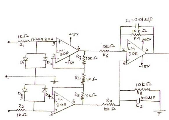
    I implemented EMG circuit using LM308 for instrumentation amplifier. This picture might give you a better idea of the same: 


    Now, instead of using LM308, I am using INA 101 and also, instead of single channel, I am designing it to be multichannel. I had a few questions about INA 101, is there any technical stuff like application or example circuits available for INA 101 (I went through the data-sheet). Also, are there any multi-channel circuit diagrams available (EMG, ECG or EEG) all are same except for filtering. 


    Thanks in advance, 

    Jainu

  • Hello sir ,can u plz attach the tina schematic for in326 amplifier

  • hello sir can u plz attach the tina schematic of the above post


    thanks and regrds

    harmanpreet singh

  • Who's design are you after? Mine was riddled with noise. It requires a lot of trial and error and playing with the right filters to get a good signal. It also depends on the application whether small or large muslce stimuli is being measured.


  • Who's design are you after? Mine was riddled with noise. It requires a lot of trial and error and playing with the right filters to get a good signal. It also depends on the application whether small or large muslce stimuli is being measured.


    Perhaps TI could provide some templates or a design guide.


  • Agreed.  Most bio-sensor designs do require careful shielding and customized application-based filtering.  Some of the circuits posted in this thread serve as a good starting point but are by no means complete.  TI does not currently have a design guide for EMG systems, but this is definitely a good suggestion and something to target moving forward.

    Matt

  • Sorry for getting this topic back from ages ago but i belive it is better than creating a new as it got a lot of good discussion in special about INA333. On my design i cant use DLR circuit as i need to go for dual electrode system. I designed a couple EMG amps in the past with the good old AD620 but using DLR circuit and it worked properly. Simple question, if i go to the ac coupled electrodes approuch following the design propoded a the ieee article, would be a problem to tie the center reference (in the middle of the resistors) to my middle reference (1.65V for instance)? An important fact is that that reference point is created spliting my supply with two precision resistors and using a OPA333 as voltage follower. I would do that so i can create the bias for the INA333 inputs and kill any electrodes offset improving my INAMP amplification. Thank you!