This thread has been locked.

If you have a related question, please click the "Ask a related question" button in the top right corner. The newly created question will be automatically linked to this question.

Noisy INA2332 or OPA2340

Other Parts Discussed in Thread: OPA2340, INA2332, LM3940

Hi everyone,

I am having some issues with noise with the INA2332 or the OPA2340. Would anyone knows where this noise comes from?

Thanks in advance for your kind help.

  • Hi Toma

    Is the noise periodic with a frequency of 50/60Hz? If so it is pick-up from the AC mains and you will need to consider shielding.

    regards

    Steve

  • Noise. The Black Art.

    You are also measuring 30mVpp at the junction of your voltage divider, but 3mVpp at the power supply node?

    -Ken

  • Stephen,

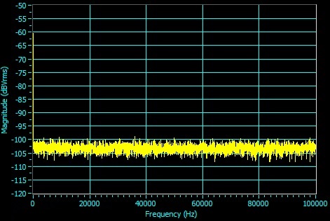
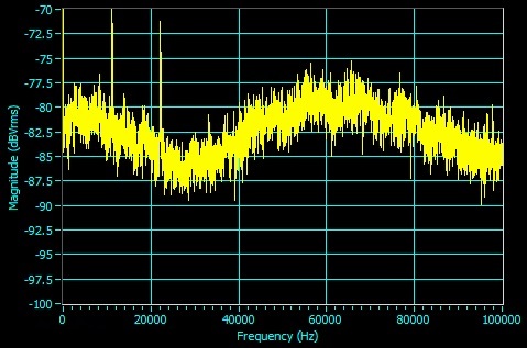
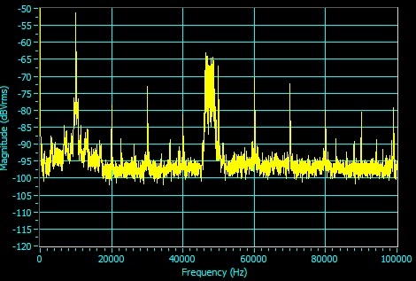
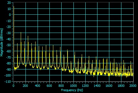
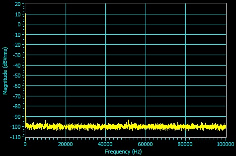
    The noise doesn't have a special frequency. I looked at the signal with a Dynamic signal analyzer and there is no particular frequency that is dominant.

    Ken,

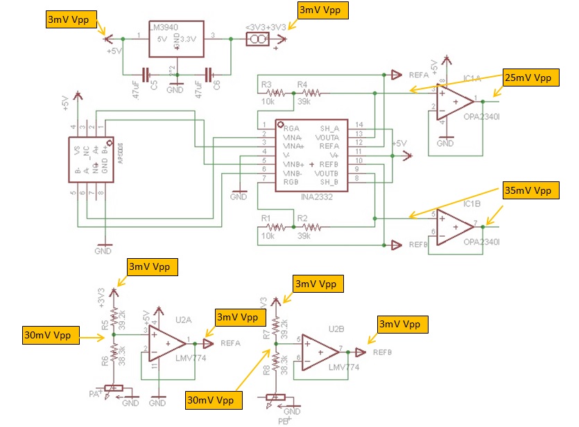
    I know, I don't understand it either. Plus after the follower the two RefA, RefB signal only have 4mV Vpp. I realized I left the 3rd leg of the potentiometer floating so I thought it was it. But I tried to connect the 3rd leg to R6 and R8 and same thing: 30mV Vpp at the junction of the voltage divider. I even connected R8 straigth to ground (shorting the potentiometer) and nothing.

    On the INA the noise seems to come up at the RGA, RGB pins.

    I upload a more detailed version of the signals I have:

    Thanks for your replies

  • Alrigth, it seems there is some parazite dominant high frequencies.

    GND is fine:

    5V isn't that great:

    The output in B has foundamental at ~11kHz:

    The output in A has foundamental at ~11kHz too:

    Voltage divider junction R7 R8 has peaks every 2000Hz plus high 11kHz:

    Voltage divider junction R5 R6 has peaks every 2000Hz plus high 11kHz:

    What would you guys suggest?

    Should I filter high frequency noise with a RC filter on the output of the INA?

    or Should I filter the +5V?

    Thanks for taking the time to read this post :)

  • Actually the 5V when it is not connected to the circuit looks like this:

    I tried to add a 150uF electrolitic capacitor on the 5V. It make the 5V looks better but doesn't change anything to the output signals of the INA.

    Also if I remove the jumper on the 3.3V line the noise on the ouput signals of the INA disappear and I get a clean signal (just not centered).

    The 3.3V signal on the output of the LM3940 looks pretty good:

    Any idea?

  • Hi Toma

    Is C5 in backwards? It looks like it on your schematic.

    Have you used decoupling capacitors on the various ICs?

    I would suggest building up your circuit bit-by-bit. Try grounding the inputs of the INA2332, for example.

    regards

    Steve

  • Hi Steve,

    Thanks for replying. I chose C5 as a ceramic capacitor. I don't have the decoupling capacitors on the various ICs but I feel that this wouldn't be it since the chips are pretty close to the .47uF.

    I tried to ground the inputs B (Pin 5,6 of the INA) and the noise disappears on the output. I guess I shouldn't have accused the INA. Sounds like the APS00B is at fault in the end. I guess filtering is the only solution to the noise then.

    Let me know if you think I am thinking correct.