This thread has been locked.

If you have a related question, please click the "Ask a related question" button in the top right corner. The newly created question will be automatically linked to this question.

OPA320 Gain Issue

Other Parts Discussed in Thread: OPA320, REF3133, OPA2320

Hi , 

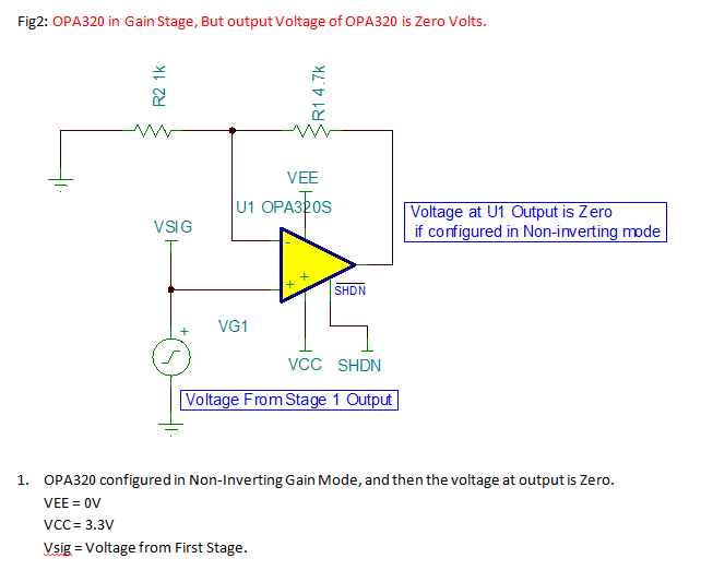
I have configured OPA320 in Non-inverting configuration with double Gain. But i found when i use a gain for OPA320 there is no output voltage. Again if i remove gain and use as buffer, then i am seeing output voltage following input voltage .

Can you help me in overcoming this issue ?

  • Hello Pavan, 

    I have moved your post to the Precision Amplifiers forum, here one of my colleagues will be able to help you.

    Regards,

      -Diego Meléndez López
       Audio Applications Engineer

  • Pavan,

    Please provide a circuit schematic of your application since it is impossible to know what you exactly mean by configuration with double gain - picture is worth thousand words (use Insert/Edit Media button above). Also, by no output voltage do you mean the output is zero?  If so, you most likely configured the circuit with a positive feedback so the output collapses on one of its rails.

  • Pavan,

    You provided the entire circuit schematic with many op amps in various configurations but without nodal voltages.  Also, you do not show the specific OPA320 in gain configuration causing the problem.  I can see that you use REF3133 with 1k/1k voltage divider to drive the non-inverting inputs of OPA2320 to 1.65V (this should be fine in follower configuration) but then you do not show the gain configuration when you run into problem.  Therefore, please show the specific circuit configuration, with all the nodal voltages, where you get “no output,” since without it I cannot determine the part of the circuit where the problem lies.

  • Gain Issue On OPA320.docx

    Pls have a look on the file, this might be more clear.

  • Pavan,

    In your document, you show completely two different circuit configurations:

    In the first circuit (see below), the DC gain is 1, thus applying few macro-volt DC signal at the input will result in the output being saturated at its negative rail.   

    The second circuit (see below) has DC gain of G=+5.7 and you should see the correct output voltage as long as you make sure to enable the part (SHDN>2.31V for Vs=3.3V) - see PDS table below.


    Also, make sure that the input voltage is large enough (Vin>~20mV) so the output is driven at least 100mV above the negative rail (within linear output voltage range of OPA320).

    I have simulated the circuit above for Vin=0 and Vin=100mV and it works as it should - see below.


  • OPA320 Gain Issue.TSCHI Marek

    On OPA320 IC if i provide DC offset on AC signal the Gain does not work. I have attached the  .TSC file.

  • You have the DC offset on your AC source set to 1.65V which times closed loop gain of 5.7 forces output into positive saturation as shown in the DC / Calculate Nodal Voltages analysis.  Always run a DC analysis before any AC analysis.  AC analysis when amplifier is in a DC saturation has no meaning.  Transient analysis will not work either.  Get the offset adjusted so the output is not in saturation....