This thread has been locked.

If you have a related question, please click the "Ask a related question" button in the top right corner. The newly created question will be automatically linked to this question.

Load Cell Sensor with INA125

Other Parts Discussed in Thread: INA125

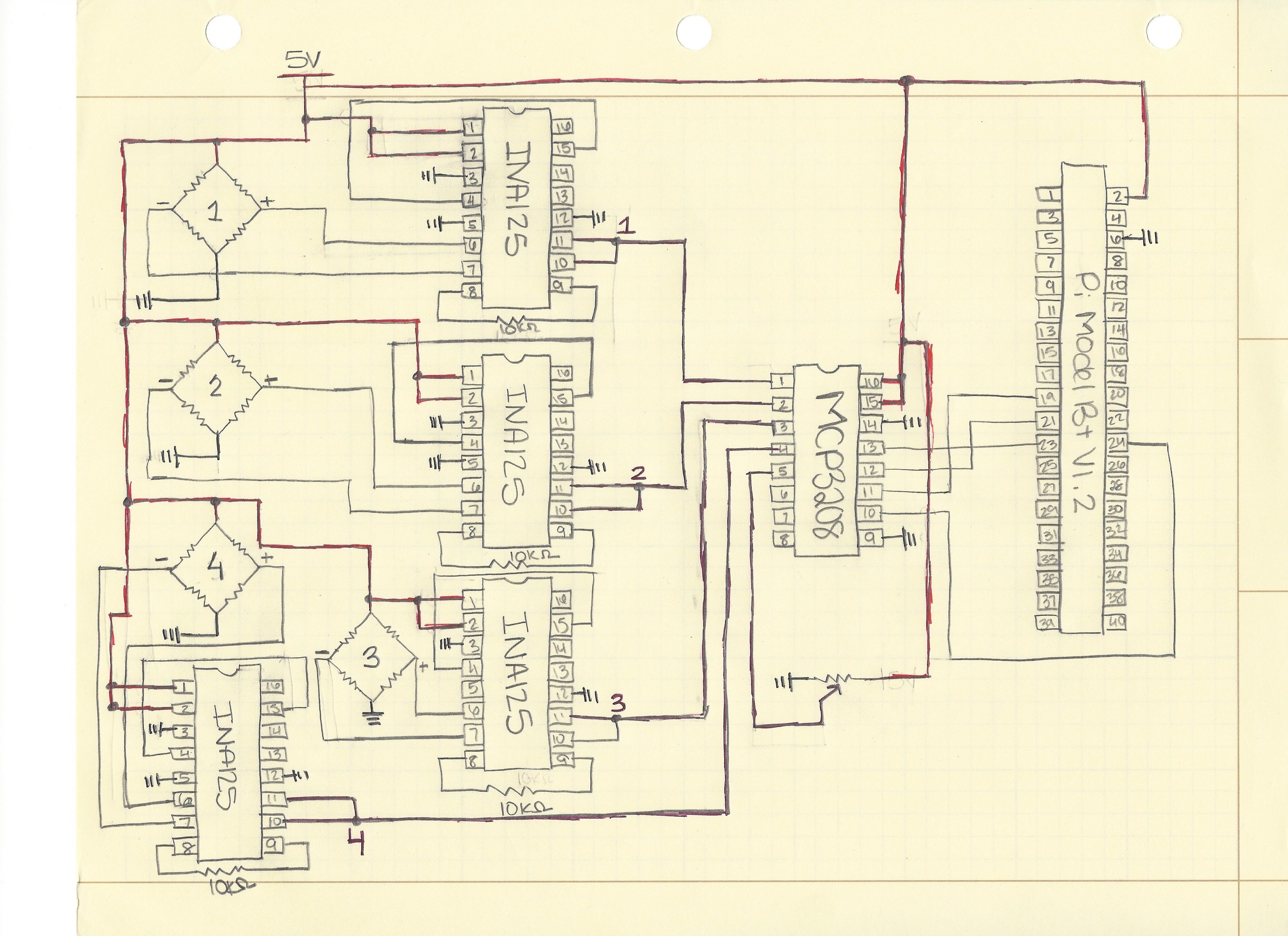
I am working on a project with the FX1901 Compression Load Cell sensor to measure weight distribution. The voltage from load cell sensor is too small to be read by the ADC, which is an MCP3208. I connected them to the INA125 before the ADC before recording the data onto the Raspberry Pi. However there is an output voltage from the INA125 with zero weight placed onto the load cell of 0.07V. I have tested the INA125 with out the full connections and there is still an output of 0.07V. I need help figuring out what is going on with the INA125. Any advice will be welcome!

  • Hello user4304888,

    The main advantage of the INA125 is the integrated precision voltage reference, which can be used for the bridge voltage. According to the diagram, however, it appears as though the bridge is supplied by the 5V external supply (in other words pins 4/15 are not connected to the bridge). In order to use the 5V reference, though, you would need a larger supply voltage (at least 6.25V). So, in the end you could use just about any instrumentation amplifier to reduce cost and complexity if not using the integrated reference.

    In order to verify operation, I would try inputting a known differential voltage with a known common-mode voltage. For example, place 2.5V on pin 6 and 2.4V on pin 7. The output should be Vout=((VIN+)-(VIN-))*G+Vref=(2.5-2.4)*10+0=1V. Once you have correct functional operation, you can then connect the bridge. Finally, please be aware of the output swing vs. common-mode relationship of instrumentation amplifiers. The operating region of the INA125 operating with a single 5V supply and Vref=GND is shown by the lower right figure on page 5 of the data sheet.