This thread has been locked.

If you have a related question, please click the "Ask a related question" button in the top right corner. The newly created question will be automatically linked to this question.

OPA1604 Catastrophic Failure

Other Parts Discussed in Thread: OPA1604

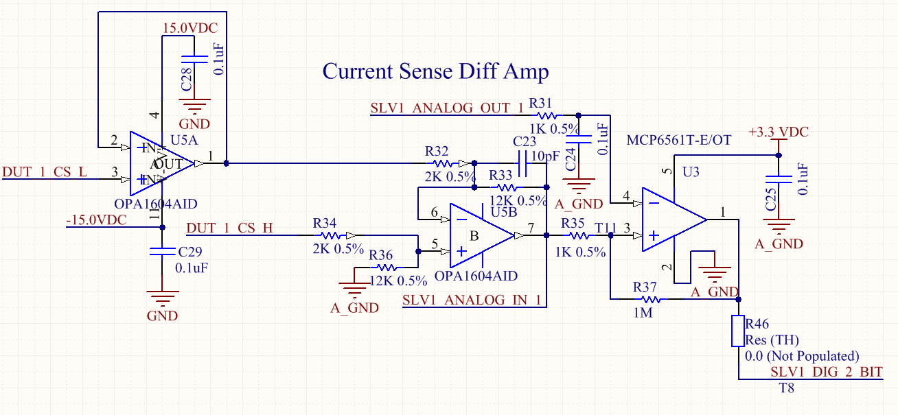
I had an OPA1604 fail in a catastrophic way.  I already posted this in the Audio forum, since it is considered an Audio operational amplifier.  However, I am not using it in an audio application.  So as to not double post, I will simply reference my post in that forum.

Thank you

  • I have a board design that used to use a Linear Technologies LT1631CS#PBF.  I switched it over to a OPA1604 because it had identical or better specs, for about 60% of the cost.  I had been using the circuit for a few months.  Today, I plugged in a sensor and I heard a "POP" sound.  The IC has a chunk of it's cover missing by pin 4.  Now, it's forcing DUT_1_CS_H and DUT_1_CS_L to the negative supply rail. What happened?  The circuit is posted below.  I will describe some of the missing details.

    The supply voltage (+/-15V) in this design is allowed to run as low as +/- 12V, which is where it is currently at.  "DUT_1_CS_H" is connected to the output of another op-amp that's used as a linear supply.  That op-amp is powered off the same supply rails.  "DUT_1_CS_L" is on the load side of a 10 ohm current sense resistor.  The current sense circuit isn't being used at the moment, so the 10 ohm resistor has a 0 ohm resistor jumper across it.  In the same way, R46 is not populated, as the circuit is not currently needed.  SLV1_ANALOG_OUT_1 connects to a D2A with an output range capable of reaching 1.4V from the supply rail (same rail that is powering this op-amp).  SLV1_ANALOG_IN_1 connects to a A2D with an input range of +/- 12V.  All grounds are tied together at a single point on the board.

    I plugged in an external device that is normally powered off the supply op-amp (not shown in the circuit).  The supply op-amp was set to 0 volts.  Immediately upon plugging it in, the op-amp blew out.  I don't understand what could have happened.  Any short would have put the pins, worst case, at one of the supply rails.  This is within the spec of the op-amp (0.5 volts beyond the rails max).  There's no other source of voltage on this board.  The outputs are all driving 1K or more.  The supply op-amp's output has a parallel combination of capacitors (330nF, 0.1uF, and 10uF), so I don't see how an ESD event could cause this.

    I have 3 more of these circuit boards, but I am hesitant to try one until I can determine what could have caused this failure.

  • Hello Jason,

    It sounds like you had an EOS event. This occurs when the absolute maximum ratings of the amplifier are exceeded, such as, the supply voltage of the amplifier is higher than the absolute maximum ratings or the input current is greater than 10mA. The absolute maximum ratings of the OPA1604 can be found on page 2 of the datasheet. It might be helpful to check out our TI Precision Labs for videos about EOS for more information.

    To help trouble shoot what occured, I think it would be best to only test the OPA1604 circuitry. Therefore, is it possible to disconnect the OPA1604 from the input circuity (DUT_1_CS_H and DUT_1_CS_L) and input a known voltage to DUT_1_CS_H and DUT_1_CS_L? I recommend inputing 0V and increasing until you reach the voltage you expect to be applied when the sensor is connected. During this time, monitor this inputs, outputs, and supply voltages on an oscilloscope. Make sure that nothing goes above the supply or is oscillating.

    If an EOS event does not occur during the testing, I will suspect the sensor some how caused the input voltage to exceed the maximum input voltage or more than 10mA flowed into the input of the device. In this case, we will have to protect the device by adding diodes from the input to the supply to prevent the input from going above the absolute maximum ratings and/or add a series resistor to the input to limit the current to less than 10mA. Or find another way to prevent damaging the device.

    It might also be helpful to test the sensor output when you plug it in to verify that a large voltage pulse does not occur that might cause an overvoltage of the OPA1604.

    Please let us know the results of the testing and post any relevant oscilloscope images.

    -Tim Claycomb

  • Unfortunately, it is not possible to disconnect DUT_1_CS_H and DUT_1_CS_L from the op-amp without physically cutting a trace on the circuit board.  I can say that any voltage going to the external sensor (discounting ESD of course), is supplied by another op-amp powered off the same supply voltages, with the same ground connections.  I can guarantee that the supply voltage is within rating.  My last measurement put it at +12V/-11.8V.  The supplies were on at the time of the event, and had been on for at least 20 minutes.

    The sensor PCB itself contains a hall sensor IC with an open collector/open drain output that is tied to it's supply voltage.  This supply voltage is provided from an op-amp.  On the sensor PCB, there are supply bypass capacitors, and ESD protection.  I cannot share the exact details of the sensor PCB, as it's the customer's design.  There is nothing on the sensor PCB that is designed to generate voltage, such as a charge pump or DC/DC converter.  Outside of ESD, it is impossible for the sensor to create a voltage pulse.

    With my project time constraints, I have had to keep going on the project.  I grabbed a replacement PCB and I haven't had any issues since.  I have been more careful to ground myself and the sensor, since that event, so I am starting to suspect it was an ESD event.  I am, after all, working in a carpeted cubical.

    Jason

  • Hello Jason,

    I am glad to hear everything seems to be working now. However, I would still be cautious because having a piece of the device blow off is likely a cause of EOS. You mention in your first post that the supply op amp has a parallel combination of capacitors on the output, is it possible that the output of this amplifier is oscillating? You would need to take measurements with an oscilliscope (not DMM) to verify this.

    -Tim Claycomb

  • Tim,

    I tried to check out the video link you posted, but the video link you posted didn't work.

    The full design of the board is a large master board that contains the driving op-amps, some A2Ds, DACs, and some micro-controllers to run it. It is designed to be universal. We then use small daughter cards that directly interface with the external device. It allows us to quickly adapt the hardware design to handle different external devices as our customer needs.

    The driving op-amp on the main board is a current feedback op-amp, running at unity gain. That board design taught me that a current feedback op-amp is prone to become unstable when running at unity gain. We have had some cases where the driving op-amp would oscillate. That was on a different daughter card. Unfortunately, that is a design choice that I will have to live with. I have had this op-amp on the scope and I did not see any oscillation, but I will not rule it out under all circumstances, due to the driving board being susceptible.

    Now, at the risk of sounding ignorant, how would oscillation cause this problem? The voltage on the input pins would be within the voltage limits of the OPA1604. I understand how oscillating the output will cause heat to build-up in the part, but I wouldn't expect a catastrophic instantaneous "POP".

    Jason.
  • Hello Jason,

    If the voltage on the input pins says within the voltage limits of the OPA1604, I too would not expect an instananeous "POP". My thought was that if the op amp output was oscillating, it could cause something else on the board to exceed the ratings of the OPA1604 and therefore cause an EOS event.

    Here is the link to the TI Precision Lab videos again.

    -Tim Claycomb

  • Tim,

    That video link works, thank you!

    Section 11.1 on ESD events was particularly helpful in explaining the operation of the "absorption device".
    It explains how the "absorption device" works, and is limited to mAs continuous current.
    I had always assumed the internal protection was simply the diodes shunting the voltage into the supplies.
    I was not aware that the diodes were, in fact, turning on an active current shunt.
    I have a far better understanding of the input protection now.

    Based on that video and 12.1, I am beginning to think that it was an excessively large ESD event that blew out the "absorption device", leaving it permanently in a shorted state. This, of course, would cause a rapid build up of heat. I could buy that this rapid heat buildup could blow out the side of the package.

    Due to project deadlines, I was forced to continue with the other boards we have in stock, and hope for the best. Fortunately, I have not had a repeat blow-out! This also leads me to believe it was an ESD event. Since, it occurred at the moment the external device was plugged in, I am thinking I must have had a huge charge on the device.

    Thank you very much!

    Jason
  • Hello Jason,

    I'm glad the videos were helpful! Please let me know if you have any other questions.

    -Tim Claycomb