This thread has been locked.

If you have a related question, please click the "Ask a related question" button in the top right corner. The newly created question will be automatically linked to this question.

Instrumentation Amp for Pressure Sensor

Other Parts Discussed in Thread: INA333, LM7705, INA326, OPA314, ADS1013, ADS1014, TIPD170

I am looking at using the INA333 instrumentation amplifier to condition a pressure sensor. The sensor has an input voltage of 10V nominal with supply current of 1.5mA. The output is from 0-100mV using an internal wheatstone bridge configuration. I would like to have an output signal of 0-4.096V or 0-2.048V, so the full dynamic range of an ADC can be utilized. I will be using the INA333 in a single supply configuration with a possible negative bias generator on V- to have the output swing to GND.

The issue that I am facing is the input common mode range versus output voltage. Is there a suggestion for a replacement part or something externally that I can do raise the Vcm close to midway of the supply. I saw a reference design that used a resistor to GND where GND is placed on the wheatstone bridge but that requires knowing exactly what the resistances are in the bridge.

Thanks

  • Hello David,

    If I understand your question correctly, you are trying to convert a 0-100mV input to a 0-4.096V/2.048V output. In this case, I can offer you a few solutions:

    1. Using the INA333 with a LM7705 to provide a -0.232V V- rail. This will allow you to get a true zero output for a 0V input and the gain for the full scale output can then be adjusted accordingly. You will have to raise your supply voltage to the midpoint if your Vcm.

    2. Using the INA326. The INA326 is a true rail to rail instrumentation amplifier that can provide a true 0V output when used in a single supply configuration. However, depending on how much current you are going to draw from the output, you may have a significant output voltage swing. It shouldn't be a problem for the full scale output, but it might affect the zero-scale output by providing a non-zero output. In this case, you might need to buffer the output of the INA326.

    If I could see a schematic for your design, I could provide a better recommendation.

    Best Regards,
    Mihir Gupta
    Field Applications Engineer,
    Texas Instruments
  • Hi Mihir:

    I do not have a finalized schematic yet, just an idea of what needs to be processed. The input is a 0-100mV output from a pressure sensor via an internal wheatstone bridge configuration. I would like an output of 0-4.096/2.048V to maximize the input range of an ADC.

    Here is the flow of the signal conditioning:

    Output of pressure transducer -> instrumentation amp -> 2nd order low pass filter -> 12-bit delta sigma ADC

    I was looking at the INA333 with the LM7705 for the int amp, OPA314 for the butterworth filter, and then the ADS1014DGS.

    Thanks

    -David

  • Hi David,

    Another option would be to use the INA326 with a LM7705 to provide the V- Rail. This will get rid of any output voltage swing issues you may have with a high load current. You can use the same LM7705 to provide a V- rail to the OPA314 filter.

    Is there a particular reason you selected the ADS1014? If you don't need the internal comparator and PGA of the ADS1014, you can consider using the ADS1013 instead.

    I think you were referring to the TIPD170 (Single-Supply Strain Gauge in a Bridge Configuration) when you were talking about the reference design with the resistance adjustment. But as you correctly said, the reference design requires you to be able to adjust the internal resistances of your wheatstone bridge. In that case it looks like your only option would be to raise your supply voltage to the required level in order to get an acceptable Vcm from your bridge. I would recommend first testing the common mode voltage output of your wheatstone bridge vs. your bridge supply voltage to see how much influence you have on the Vcm of your bridge.

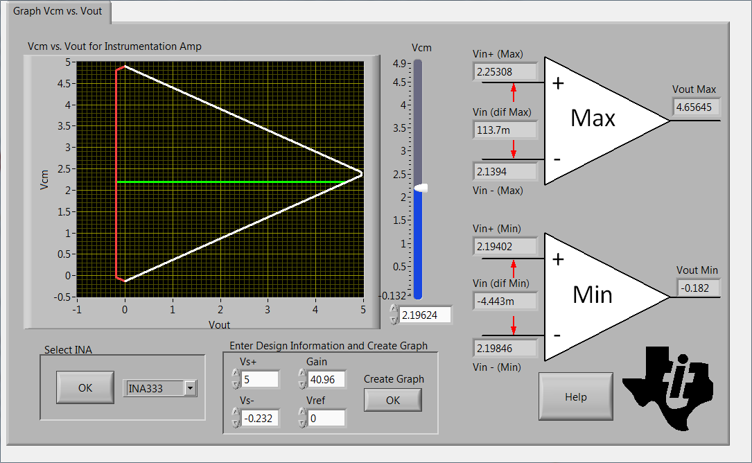
    Using the INA333 and LM7705, I have the following Vcm vs Vout curve:

    So for a 4.096V output you'll need a Vcm of around 2V. You can download the tool and adjust the parameters for yourself from the link below:

    Please also take a look at the TI Precision Labs Video Series about OpAmp input and output limitations for a more in-depth explanation about Vcm vs. Vout.

    I hope this helps. Please let me know if you have any other questions.

    Regards,

    Mihir