This thread has been locked.

If you have a related question, please click the "Ask a related question" button in the top right corner. The newly created question will be automatically linked to this question.

INA2128 output limiting problem

Other Parts Discussed in Thread: INA2128, INA128, INA2126, INA126

Hi,

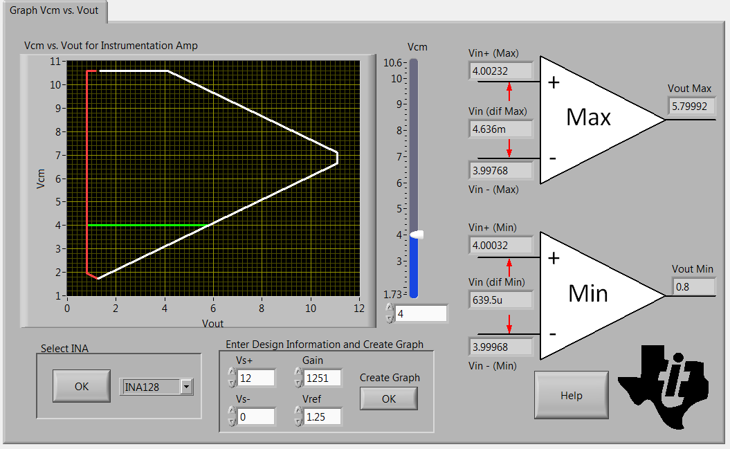
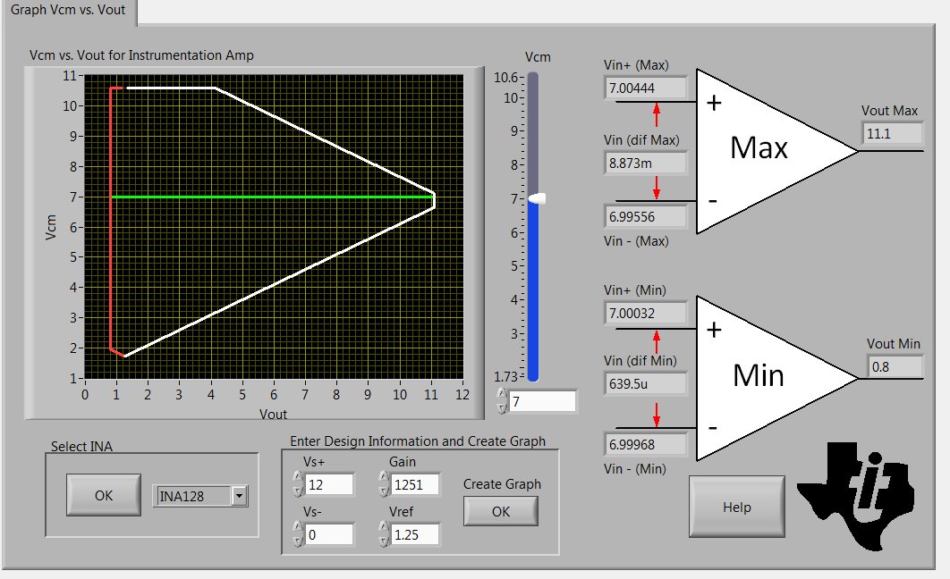
I'm having a problem using the INA2128 with a load cell resistive bridge. circuit attached. The impedance of the bridge is approximately 1K. The exitation on the bridge is 8VDC. So the common mode voltage is about 4V. The bridge puts out a maximum differential voltage of 8mv. The supply for the INA2128 is 12VDC and GND. The reference voltage is 1.25VDC. I have a gain resistor of 40 ohms for a gain of 1251.  A 10K resistive load on the output.

What i am seeing is the output limits to about  5-7volts? Looking at the data sheet I don't see why this should happen? I simulated it in TINA using your spice macro for the INA2128 and I see the same limitation. What is going on? Please HELP! 

ThanksRECYCLEnew-4-1-16-5B-6-27-16-4.pdf

  • Hello Jerry,

    I can tell that you have a Common Mode Voltage limitation problem. Putting your design information into TI’s Input Common-Mode Range Calculator, you can see that your minimum and maximum output voltage is 0.8V to 5.7999V. This is represented visually by the horizontal green line in on the graph.

     Also note that the INA2128 is the dual package version of the INA128 which allows us to specifically calculate the graph for your device. 

    By going outside of these limits, the amplifier acts non-linearly (distorting the signal) which can explain why your output is not linearly related to you input. In fact, your Vout should be around 11.258V. This is calculated from Vout_max = Vdiff * (Gain) + Vref --> Vout = (8mV)(1251)+(1.25V).

    Ideally, you want to have your output voltage range be as wide as possible. This can be achieved by moving your Common Mode Voltage. In the figure below the Common Mode Voltage was set to 7V instead of 4V using your design information and the output voltage range increased to 0.8V to 11.1V. Notice how the size of the green line has now increased.


    I highly encourage you to download the calculator using the link at the end of this post, look into changing your design information (Vs+, Gain, Vs-, and Vref), and see if you can get your Common Mode Limitations to match up with your desired output voltage. Increasing your Vs+ and changing your Vcm for example could help you achieve your desired output.

    If your system is not calibrated, I encourage you to look into smaller tolerance gain resistors otherwise the introduced gain error can give you unexpected values at your output. Also, always make sure you measure voltages from the pins of the device for the most accurate readings and keep Vref a low impedance node to avoid degrading your CMRR.

    If you are interested in using this tool, you can download it here: http://www.ti.com/tool/ina-cmv-calc

     Also, if you are interested in learning more about the Common Mode Voltage limitations and the generation of this graph, you can find it here on the Precision Amplifier Wiki: https://e2e.ti.com/support/amplifiers/precision_amplifiers/w/design_notes/3373.understanding-instrumentation-amplifier-vcm-vs-vout-plots

     In addition, if you are interested in seeing other common problems with these kinds of circuits and learning about them, check out TI Percision Labs:  http://www.ti.com/lsds/ti/amplifiers-linear/precision-amplifier-precision-labs.page


    Best,

    Cole Macias

    Precision Analog


  • Cole,

    Thank you very much. That explains it and the tool is great. I wish I would have known this earlier,  I originally just used the data sheet and the graph of the common mode range looks like my conditions are within the window of accepted operation.

    We already made prototype production boards and will have to now make a modification. Our previous rev board used an INA126, which worked fine and shows a max output voltage of 11+ with our same conditions using the tool. I choose the INA128 because of the laser trimmed offset and  the SOIC pinout for both the INA2126 & INA2128 are the same, thinking I could use either part. Unfortunately I now see the SOIC  packages are different widths.

    Anyhow, thanks again for your very quick response and I have to say the part is extremely stable and repeatable.

    Regards,

    Jerry