A related question is a question created from another question. When the related question is created, it will be automatically linked to the original question.
If you have a related question, please click the "Ask a related question" button in the top right corner. The newly created question will be automatically linked to this question.
I am unaware of any such stand-alone calculators or spreadsheets at this time. The closest thing I can think of is the error calculation I performed for TIPD156. The calculations were done with Mathcad and the source file is available in the "Other" Directory found in the design's zip file. I hope this helps!
I will take a look at the design files you mention, but I do not have access to Mathcad.
I will have to resort to Excel.
However, I refer you to some further questions on the INA826 if you would be kind enough to progress this
Clarification on noise calculation:
Concerning the data sheet, on page 25. Table 2. provides an example design. In the resolution section there is a voltage noise calculation using a BW of 1kHz but an extra term to translate the noise RMS noise into a PPM figure.
Where does the "6" come from in this example (the term it appears in is 6/VDIFF in the equation? Figure 6.2 provides the example design but does not mention a figure of 6, and the only figure I can find in the datasheet spec relating to 6 is 6kHz -3dB BW for a gain of 1000, which does not fit this design and given the noise BW I quoted as 1kHz in the Table 2 example.
The noise equation states a 1kHz BW but the figure 6.2 states the signal frequency is 5kHz. Given the design is 5kHz and shows no filtering, Therefore the figure used should be 5kHz in the calculation not 1kHz? It does not make any sense to multiply by 6 the result. The more accurate use case is to calculate the noise based on a 5kHz BW not 1kHz as I can see for the example.
Is there a missing bracket in the Noise equation? There is an opening bracket but no closing bracket under the sqrt(Noise power) calculation? As the equation is written the "6/VDIFF" term is outside of the SQRT term thus the RMS noise voltage is then modified by VDIFF to obtain error. Apart from the "6" this looks correct.
As the example uses the datasheet specification for eNI and eNO can this be assumed to be a worst case value or simply a working figure for an error budget?
Question on IOS
for calculation involving current, is maximum Rs+, Rs- taken to be the sum of the resistances, the difference or different resistances due to tolerance?
In the calculation for offset current drift, there is no figure stated in the specifications for accurate drift: it must be inferred from the figures which I estimate to be (using worst case figures, 10nA (between -40 -> 125 degrees) minus 5nA maximum = 5nA/160 deg = 30pA/deg C. Assuming this is correct, and this is a worst case drift figure, the question then relates to maximum Rs+, Rs- above.
Based on the clarification on the above I can then understand the total error contribution to my design.
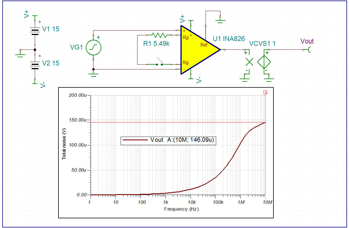
First, calculate the noise BW as described in the presentations. It is BWn=1.57*BW=1.57MHz.
Now calculate the noise RTI according to the equation on page 3 of the data sheet (note 3). Same equation as in the Table, but as you mentioned it is missing a parenthesis. I calculate 116.73nV/rtHz (notice output stage noise dominates in low gain). Now multiply that value by the square root of the noise BW to obtain the noise RTI as a RMS value. I obtained 146.26uVrms. From here you can multiply by 6 to obtain the noise in volts peak-to-peak (146.26uVrms*6=877.6uVpp) as covered in the links above. Converting to ppm is shown below:
(877.56uVpp/1Vdiff)*100=0.08776%=877.6ppm
This seems to correlate well with the simulation as shown below. Please note that our TINA models use typical values. For the INA826 noise, however, it seems as though there is not too much difference between the two (18nV/rtHz vs. 20nV/rtHz and 110nV/rtHz vs. 115nV/rtHz). Also please note that noise is really an ac error and can be reduced by filtering.
The RS resistors noted on the first page are only necessary as described in the Input Protection section of the data sheet. They were not required during characterization. The "maximum" value is 10kohms. You can use a larger value if you like, but it's really unnecessary since the 10kohm resistors will limit the current sufficiently as shown in Figure 18 of the data sheet.
The maximum offset current drift is specified in the table as 10nA over the temperature range -40C to 125C. For the error calculation it was approximated as ~60pA/C (10nA/(125C-(-40C))). For a better understanding of the offset current drift, please refer to Figure 32 in the data sheet. Multiplying 60pA/C by the temperature change (105-25) yields 4.8nA. We calculate the error as follows: (4.8nA*10kohms)/1V*100=4.8m%=48ppm.
thanks very much for your informative answer, and the information provided.
In summary, I got the 116.73nV/SQRT(HZ) initially as a noise calculation originally, but your explanation allows me to (more) accurately, assess the noise contribution to error in circuit. I notice you are using BW of 1MHz in your example and not the signal bandwidth of 5kHz to factor in total noise contribution from the amplifier. In reality my is bandlimited to < 1kHz, pre amp and post amp.
Your explanation on bias current drift is also very useful.