This thread has been locked.

If you have a related question, please click the "Ask a related question" button in the top right corner. The newly created question will be automatically linked to this question.

OPA659 High Speed Measurement System

Other Parts Discussed in Thread: OPA659EVM, ADC12J4000EVM, LMH5401EVM, TINA-TI, OPA659, OPA656, LMH5401, OPA653

Hello,

We have been working with the TI E2E community to develop a high-speed solar cell open-circuit voltage decay measurement system.  We have the following setup:

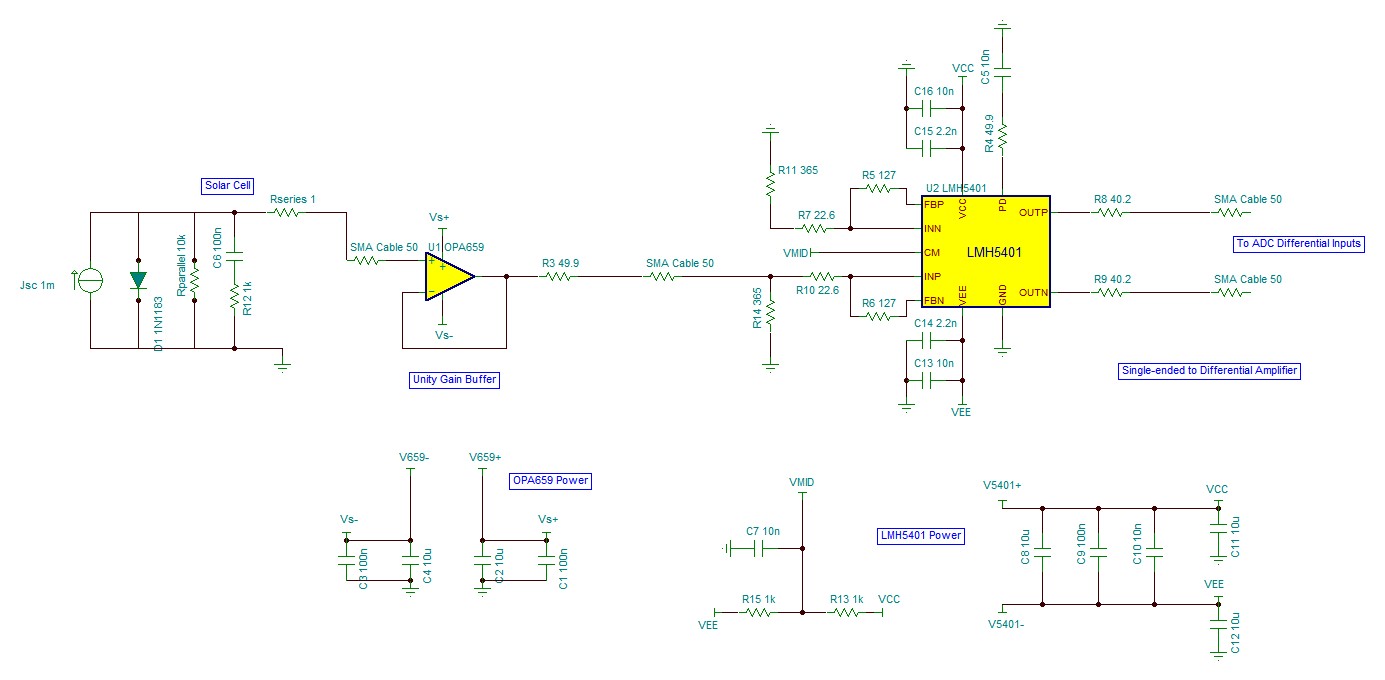
Solar Cell (device under test, single ended output) --> OPA659EVM (unity gain amplifier with the 50 Ohm resistor going from the non-inverting input to ground removed, single ended output) --> LMH5401EVM (single ended input to differential output with common mode voltage set to the optimum for ADC) --> ADC12J4000EVM (high-speed ADC) --> TSW14J56EVM (high-speed data capture board).

The 50 Ohm resistor (going from the non-inverting input to ground) on the OPA659EVM baord was removed because we need to measure devices under the open-circuit condition.  This resistor does not allow the open-circuit condition for the device under test.

The issue we are having is that there is both high (~1MHz) and low (~1 kHz) frequency noise in the measurements of the open-circuit voltage decay of solar cells.  The noise is dependent on the capacitance of the device under test.  Is there any method of eliminating this noise?

Thanks,

Alex

  • Alex,
    Have you tried simulating your circuit in TINA-TI? I am not quite sure what capacitance you are referring to over here. Can you please attach a circuit schematic of your setup?

    -Samir
  • Hi Samir,

    I have not tried simulating this circuit in TINA-TI.  Since I've never used it before, it will take me some time to do so.  I have attached a circuit diagram that shows everything except the ADC.  Capacitor C6 in the solar cell's equivalent circuit is the capacitance I am referring to in my previous message.  It is highly variable (not necessarily 100 nF).  Is there anything you can see that might produce the ringing that is interfering with our measurements?

    Thanks,

    Alex

  • Alex,

      So you have a current output from the solar cell and the output signal is connected to the amplifiers high impedance non-inverting input? That is strange. Usually when I see a current output I expect to configure the amplifier as a transimpedance amplifier.

    -Samir

  • Samir,

    Yes, you are right, there is typically current output from the solar cell, but our measurements are looking at a different aspect of the solar cell.  The constant current source is the current that is generated by light.  If we keep the solar cell in the open-circuit condition, the light-generated current will build up inside the solar cell to produce an open-circuit voltage (until the rate of recombination equalizes the current generated by light).  Then, when the light is turned off, the constant current source goes to 0 mA, and the charge carriers that were generated by this source inside the solar cell will recombine.  When the charge carriers recombine, the open-circuit voltage will decay.  It is this decay mechanism that we want to measure.  And that is why we need high impedance for this measurement.  We don't want any current flowing out of the solar cell.  Let me know if this doesn't clear things up.

    -Alex

  • Ok Alex,

    I think I now understand what is being measured. The OPA659 is not the ideal amplifier for what you are trying to do. Its voltage noise is quite high. The OPA656 has slightly lower noise. There are other amplifiers as well that have still lower noise. Can you please let me know:
    1. Bandwidth requirement
    2. Input Voltage range.
    3. Power Supplies available.

    The next thing I would do is to eliminate the LMH5401 for now and try isolating and optimizing the 1st amplifier using a scope since this is going to be the major noise contributor.

    -Samir
  • Hi Samir,

    1. We want as much bandwidth as possible, but will be limited by the resolution of the ADC which can sample at a rate of 4 GS/s.  So, I would say that having a bandwidth in the GHz would be fantastic, but may not be possible.  I don't know of too many suitable opamps that have a bandwidth in the GHz range.
    2. The input voltage will be from 0 VDC to 1.2 VDC, and the decay will take place between these two values
    3. Almost any supply voltage is available.  Right now, I have the OPA659 powered by a +/- 5V supply.  But it would be easy to adjust the power supply to the opamp.

    I looked at the specs for the OPA656, and the slew rate is 10 times lower.  I would say that this is absolute minimum slew rate that is acceptable for this application.  There are transients in the decay that occur on the order of nanoseconds, and can have drops in the open-circuit voltage on the order of tenths of a volt.

    The voltage noise is not much lower with the OPA656, and the bandwidth is just slightly lower as well.

    I would like to point out that while a buffer amplifier is needed for this application, it does not necessarily have to be unity gain.  So long as there is a linear relationship between input and output and the ADC's voltage limits are not exceeded, then it should be fine.  Not sure if this will helpwith the design.

    I'll check how things look at the output of the OPA659.  Thanks for the suggestion.

    Thanks,

    Alex

  • Hi Alex,
    Ok so there are fast transients; when you mentioned decay I was hoping that the bandwidth need was not too high. The OPA653 is another option, fixed gain of 2V/V (6dB) and similar slew rate and bandwidth with 30% lower noise. I think that's the best solution I can think of as of now. Hope this is helpful.
    -Samir
  • That does look like a better option. We'll hold off on purchasing another opamp until I look at the output of the OPA659. Thanks for the help. I'm sure I'll have other questions down the road.

    -Alex