This thread has been locked.

If you have a related question, please click the "Ask a related question" button in the top right corner. The newly created question will be automatically linked to this question.

How can i reduce current to less than 4mA

Other Parts Discussed in Thread: MSP430F4152, OPA317, OPA330, XTR117

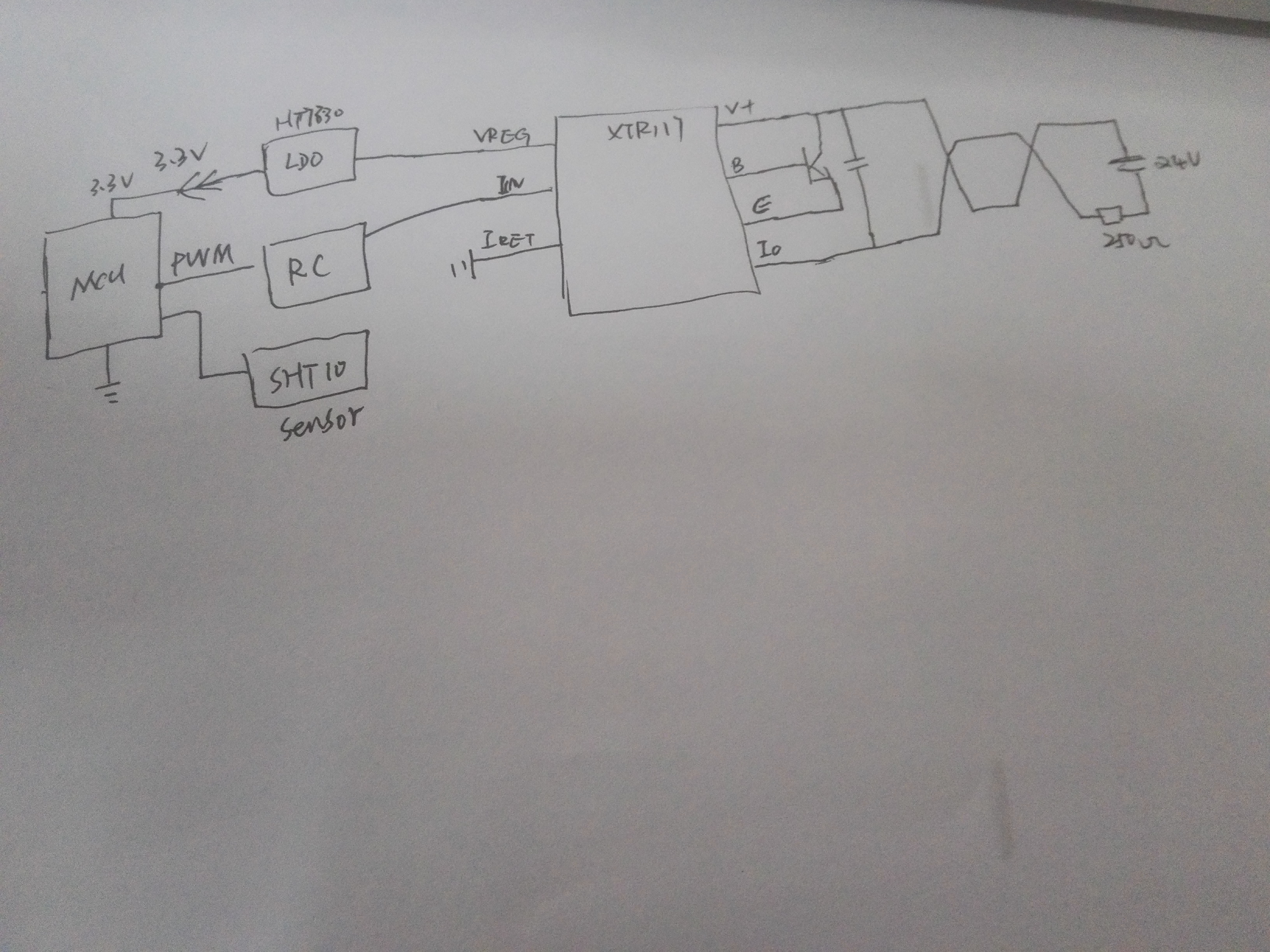
My MCU is MSP430F4152   current consumption 0.5mA   use  PWM  to  Iin   RC to Iin use 12K resistance ,But i test IO pin current is 4.12mA  i change PWM  duty cycle but 4.12 is minimum, i do not know which IC consume more current?  how can i test?

  • Hello,

    There may be a few things going on in your design that are preventing from working as desired.  First, what is the SHT10 sensor?  Could you send me a link to the product datasheet for this sensor so we can take a look?

    Depending on the PWM frequency and capacitance on the line you may be consuming more current than you expect.  We've had good results using a design similar to the one shown below.  The design used a digital isolator to accept a PWM input from an isolated input source but you can directly connect the MCU PWM output to the low-pass filter if your system doesn't require isolation.  We used a 4th order filter to achieve 12-bit noise levels from a 16-bit timer.  We recommend adding the buffer op amp to provide a low-impedance output to drive the current input of the XTR.  A low current dc accurate device such as the OPA317 or OPA330 would work well. 

  • SHT10  datasheet     www.sensirion.com.cn/.../

    My product is a  temperature and humidity transmitter, msp430f4152 with a lcd  ,PWM is 15HZ  RC is  2RC   R1 240 C1 1UF R2 100 C2 1UF  

    I set PWM duty cycle is 0  but i test the 250R Rload current is 4.12mA  not less than 4mA, i do not konow why? 

  • Hello,

    Which OPA part number did you use?  You'll need to select a low quiescent current op amp for this design.  Consider the devices that were suggested in the previous post.  

    One clue to this issue is that you haven't included an offsetting resistor, shown as "Ros" in the schematic I attached earlier.  Without this offsetting resistor a 0V input to the XTR117 will result in the minimum output the transmitter can produce which is roughly equal to the supply current of all of the sensor transmitter circuitry powered from the loop.  In your system a 0V input results in a 4.12mA output which indicates to us that the current drawn by your sensor transmitter circuitry is roughly equal to 4.12ma (including the power supply current of the XTR117). 

    If you've already used a low current op amp then let's try to minimize the variables to see if the issue is improved.  First, try disconnecting the LCD screen to see if it is drawing more current than expected.  If that does not cure the issue then try disconnecting the SHT-10 sensor next to see if the current reduces to a level below 4mA.  Make sure you leave the PWM and timer circuitry active during the testing.

    Finally,  you may have left it out for simplicity but have you placed the datasheet recommended input/output capacitance on the VREG output and +3.3V LDO circuit?